 |
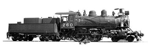
Louisiana, Texas & Pacific Railroad Southern Pacific #260 |
Nov 2018 / RWH
Nov 2018 / RWH
Nov 2018 / RWH
Nov 2018 / RWH
Nov 2018 / RWH
Prototype
 he San Antonio & Aransas Pass Railroad (SA&AP) took delivery of #60, built by Baldwin, in 1922. Southern Pacific took control of the SA&AP in 1925, and used the newly numbered #220 (renumbered 1950) until 1954. It was sold to Paulson Spence and the Louisiana Eastern in 1954 as their #2. After Spence died the loco was sold to the Stone Mountain Scenic Railroad in 1962 and named "Texas II." The SMSRR used the loco into the 1980s, with its last runs for show and only with enough steam to keep the running gear lubricated and to blow the whistle. As of this writing, the engine is still in Georgia (see Durden photo, below).
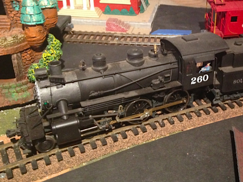
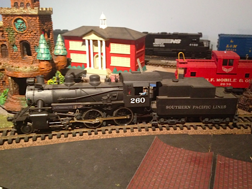
SP #260 was not the largest 4-4-0 on the system, but it is very modern for an American type. Made for light track, the locomotive was light on its feet and at home with freight or passenger trains.
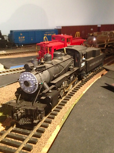
I built an O scale model of SP #260 because I like its lines and its history on the Texas & New Orleans, part of the SP Lines system. I also like the fact that it still exists. Like the O scale model, the 1/8-scale #260 will have an electric tender drive. Where the O scale model transmits power from the tender-mounted motor to the drivers through a gear box, the 1/8-scale model will have motors mounted on the tender trucks for power.
Read more about the San Antonio & Aransas Pass Railroad.
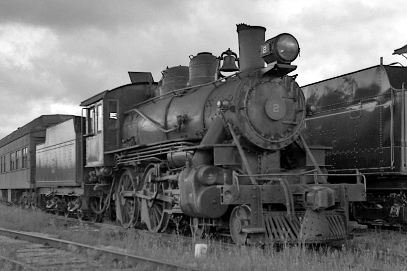
Louisiana Eastern #2
Shiloh, La / Apr 1958 / JCH


Louisiana Eastern #2
to Southern Pacific #220, later #260
to Louisiana Eastern #2, 1954
to Stone Mountain Scenic, 1962
to Knoxville & Holston River
stored out of service
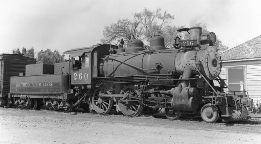
Southern Pacific #260
Gonzales, Tx / Oct 1950 / Friends of SAAP 60

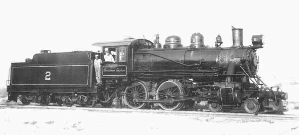
Louisiana Eastern #2
Shiloh, La / collection
collection
Southern Pacific #260 prototype drawing / collection
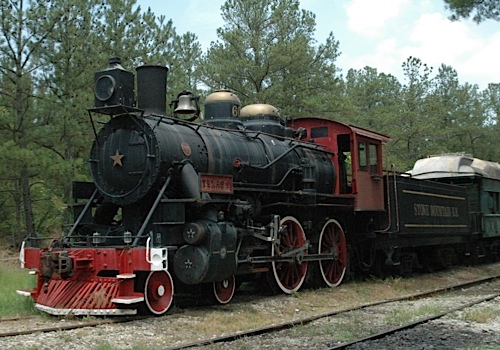
Stone Mountain #60
Stone Mountain, Ga / Jul 2007 / Andrew Durden
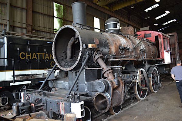
Knoxville, Tn / May 2015 / James Payne
When James and Price accompanied me to Chris' house in May 2015, we stopped at the Knoxville & Holston River shops in Knoxville. This railroad runs the Three Rivers Rambler, a steam-powered excursion trip that operates on weekends in the summer. Railroad General Manager Scott Ogle gave us a tour and told us about how they were restoring SP 260, a T&NO 4-4-0 built in 1922 for the San Antonio & Aransas Pass RR. They obtained the loco from the Stone Mountain Railroad in Georgia. The basic premise is that the loco is in fair shape and they are taking their time to do the work. While it may be years, the loco is expected to join their current stable of ex-Mississippi Railway 203 (2-8-0) and ex-Southern 154 (2-8-0). James took the photo (above, right).

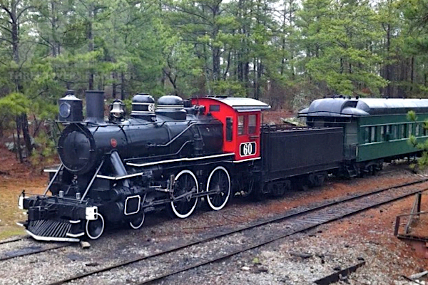 No. 60, also known as "The Texas II", was built in 1922 by the Baldwin Locomotive Works for the San Antonio and Aransas Pass Railway in Texas. The steam engine later operated on various shortline railroads in Texas and Louisiana, as well as the Southern Pacific Railroad. In the early 1960s, No. 60 was moved to the Stone Mountain Railroad in Georgia for use on its loop railroad, where it operated under steam for many years. In recent years the steam engine was placed on static display at Stone Mountain.
The Three Rivers Rambler acquired the 4-4-0 from the Stone Mountain Railroad in March of 2013. The locomotive was shipped by truck to G&O's Knoxville & Holston River Railroad, where it is being restored.
No. 60, also known as "The Texas II", was built in 1922 by the Baldwin Locomotive Works for the San Antonio and Aransas Pass Railway in Texas. The steam engine later operated on various shortline railroads in Texas and Louisiana, as well as the Southern Pacific Railroad. In the early 1960s, No. 60 was moved to the Stone Mountain Railroad in Georgia for use on its loop railroad, where it operated under steam for many years. In recent years the steam engine was placed on static display at Stone Mountain.
The Three Rivers Rambler acquired the 4-4-0 from the Stone Mountain Railroad in March of 2013. The locomotive was shipped by truck to G&O's Knoxville & Holston River Railroad, where it is being restored.
 O Scale Model
Feb 2012 / RWH
Feb 2012 / RWH
Feb 2012 / RWH
Feb 2012 / RWH

See also our LT&P Indoor Division O Scale scrapbook
Construction Notes
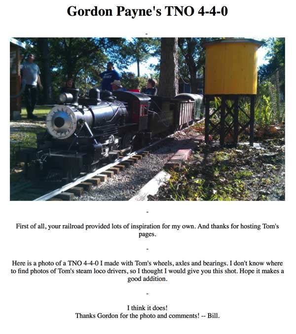
Southern Pacific #260 scale riding plans / Gordon Payne
Frame
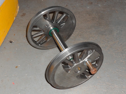
The drivers for the 1/8-scale SP #260 are from Tom Bee. Santa Clause had them made for me and delivered them on Christmas morning, to the delight of my children. They represent fairly heavy drivers, a scale 58” in diameter. The real #260 ran on 62” drivers. Tom included roller bearings and key ways that hold the drivers in precise quarter. The crank pin holes were also drilled and tapped for 3/8-16 bolts. The drivers and pilot wheels have bearings, but no bearing blocks, which is why I have to have some made.
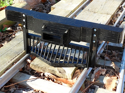
I recently built the pilot for the developing SP #260 model. It has 31 separate parts, not including bolts or handrail stanchions! I am amazed at how many parts it takes to build something like that. In O scale, you pay $5 and you have the part. In 1/8-scale, you buy the oak for the pilot beam, the brass for the spokes and the aluminum for the rest, then have to put it all together! I think I ended up drilling 66 holes, but it is not quite done.
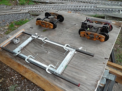
The truck kit for my steamer project arrived late last week. Over the weekend I was able to make some modifications and get them assembled. The modifications included adding a new top bar to make the trucks taller, and placing a non-operational bolster guide. Both were ways to improve the trucks to make them more like the ones in the photos. This is the original Plum Cove Studios truck set up. The top and bottom bars of the truck are interchangeable parts. The trucks on the L.E. #2 show a taller truck where the top bar is much higher. The bolsters on the truck are quite sturdy, riding on 5/16" bolts with two springs over each bolt. However, the prototype photos show a truck with a much more heavy-duty-looking bolster support set up.
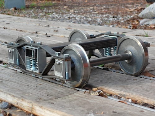
My modifications included making new top bars from 3/16 x ¾ inch steel and adding a piece of 1/8 x 1 inch aluminum to simulate the bolster/side frame interface. This set up makes the truck 3/16 inch taller at the bolster and about ¼ inch taller at the top bar. The new piece of aluminum has no effect on the operation of the truck. Although they are clamped in place with a piece of wood to keep them from flopping over, the motors will be mounted in this vertical position.
The motors, gears and axle sets are also from Plum Cove Studios, as is the control board and hand-held throttle unit.
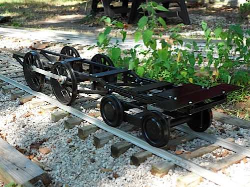
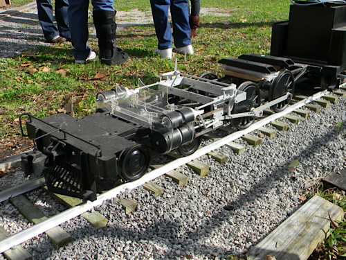
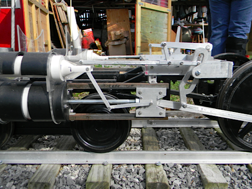
The photo above shows the frame sitting on the track, with a piece of PVC supporting the frame over the pilot truck (I have yet to install the truck mounting pin). My friend Charlie did the welding on the frame, which is very free rolling. I erred when I laid out the welding jig for the frame. The front part was too low, the result of drivers that are slightly smaller than scale size and pilot wheels that are lightly larger. I had to cut the front part of the frame off and re-mount it 1/2" higher. I notched the frame to clear the rear pilot wheel (as suggested by Charlie). The new brackets that hold the frame together are made from 3/16" x 3/4" steel.
The pilot truck is a story in itself. A friend had welded one of the side frames together (the side close to the camera). For whatever reason, he was not able to successfully complete the other frame. After waiting two months, I made new pieces, drilled and bolted them together. You can see the springs (1/4" x 3/4") that my friend Bob acquired holding the bearing blocks in place. The springs are stiff, and I may end up with just one spring on each bearing. It will depend on the finished weight of the loco. On a model this size, the pilot truck really does lead the loco through curves. Here, the truck is only about 1/2" off-center; on this stretch of 25-foot radius track, the lead driver's flange was not touching the outside rail.
This is the first time I have had the loco frame on the rails. The counterweights on the drivers are much heavier than the side rods, making the loco roll strangely. Gives me more respect for what real steamers did to track!
test run of operating chassis / Feb 2012 / RWH
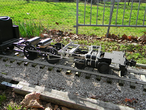
Feb 2012 / RWH
Feb 2012 / RWH
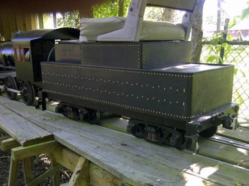
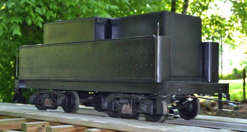
Tender
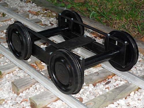
I started the locomotive's tender by acquiring a pair of arch bar trucks with two powered axles from Plum Cove Studios. At the time, I was not aware of the availability of Andrews trucks, a more prototypical style for SP #260. However, I soon learned of the Andrews trucks from Wayne Godshall of Godshall Machine Works. Wayne's side frames use the same size bearings as the Plum Cove axles. While the Plum Cove axles are a bit shorter than the Godshall versions, they fit the side frames; I added some washers to keep the axles centered, but no other modifications were needed! Incidentally, the Godshall axles also fit the Plum Cove arch bar trucks, which will end up on a flat car in the future.
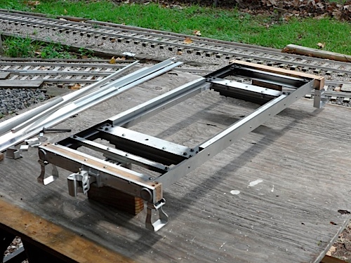
I used 3/4" square aluminum tubing and 3/4" steel tubing for extra strength. The body bolsters are 3/8" x 2" x 7.25" steel from Precision Steel Car Co., drilled and tapped for 3/8-16 bolts. Cross braces are 3/4" square and 1/8 x 2" aluminum, securely bolted with 10-24 machine screws to the bolsters and the side rails. When the frame was complete, I took the 10-24 nuts off and added Lock-tite to be sure the frame stays together. The end sill, coupler pocket and coupler are from Cannonball, Ltd. I needed a sprung, top-release coupler (for smooth coupling and prototype style). The aluminum parts are easy to clean up and drill. To end up with an end sill that was roughly square, I added three pieces of 1/4 x 1 1/2" oak and bolted the end sill to the wood parts. I also added pieces of 1/8 x 3/4" aluminum bar stock to fill the recessed part of the Cannonball end sills to more closely resemble the real tender's.
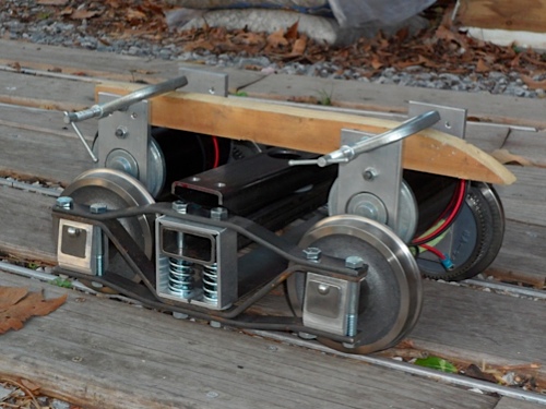
The steps are 1/16 x 1" aluminum. I used two pieces of stock so that I could bend them at the same time, creating two nearly identical steps. I did the same for the front steps, although they have a different shape and required different techniques to form. All bending was done by hand, using ¼" aluminum bar stock as clamps to help get sharp angles on the bends. The front sill is a 1 1/2" square, solid piece of oak, cut 14 7/8" long. It is mounted to the front of the frame with 10-24 screws. I mounted the power truck on the front bolster, so the motors would be close to the control board. To keep the motors oriented properly, while allowing enough play for the trucks to follow track variations, I loosely mounted two pieces of 1/4 x 1" aluminum, drilled to match the holes already in the Plum Cove motor mounts.
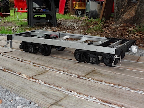
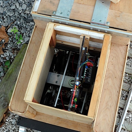
The batteries for the electric drive are situated in the center part of the tender, under the raised portion of the water tank. I put three pieces of 1/8"-thick aluminum on the bottom of the frame, mounted cross-wise, to support the batteries. The center cross piece also supports the brake cylinder and lever. I had to counter sink the screw heads so that the batteries could sit flush on the cross pieces. The fit of the batteries ended up being very tight in the front-back dimension, but about 1" of space on the sides of the batteries allows ventilation.
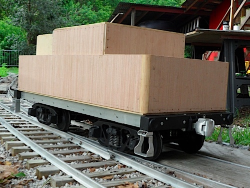
I cut the tender tank panels from 3/16" luan plywood. It is very smooth. I did my best to carefully measure and use a guide when cutting with my circular saw, to be sure the panels were all the same height. All the wood parts are glued together; I held them together with clamps and #2 x 1/2" wood screws while they dried. The tank has two sizes of side panels; the batteries sit within the wide, tall part. The oil tank at the front of the tender holds the control board. My wife Alicia had a great idea: put guides in the tank so the board can be slid in or out. This worked out very well when I connected the board. I placed a removable top on the oil tank.
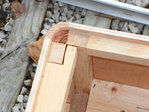
All the curved corners are made with 11/16" quarter round. To simulate the raised lip on the tender tank, I planned for the 3/16" plywood sides to sit slightly higher than the deck. I cut the quarter round with a Dremel tool to continue the lip around the corners. The top of the water tank is hinged so I can easily access the batteries for charging. I mounted the hinges to a piece of ¼ x 1" aluminum securely fastened to the front edge of the tank and added two pieces of 1/8 x 2" aluminum to the top to support the seat. I used 3/16" half-round from my local hobby shop to represent the round beading on the top lip of the tank. I removed all the wood screws I had used to hold the tank parts together when gluing (I plan to replace them all later to represent rivets). When I had sanded the entire tank, I coated the whole thing, inside and out, with sanding sealer. A couple of days later, I lightly sanded the outside again, and painted it with Rustoleum gloss black.
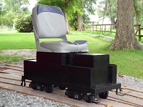
As of 8-31-11, the tender was in operating condition, with the control board installed and hooked up. I had even installed two ½" bolts on the front part of the tender as foot rests (they slide in and out as needed).
Boiler
Do you think I should open a company and call it ALCo Marrero? I started building the boiler this weekend.
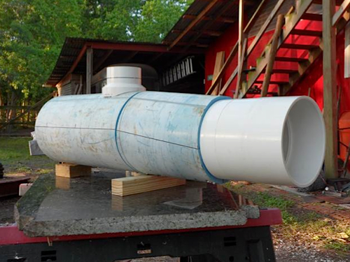
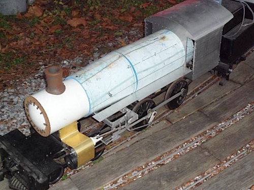
The boiler is 8" PVC, with 6" PVC couplings for the smoke box. One piece of 6" PVC runs through the center of the boiler to keep things lined up. The steam dome is a PVC 4" by 3" reducing coupling. If you ever wanted to do something difficult, try to cut a round fitting to fit a round boiler! The line you see on the dome is where I have since cut it to create the right height. A huge THANK YOU goes to my friend Jimmie Mims for providing the 8" PVC. It was the perfect length to make the entire boiler segment of the locomotive.
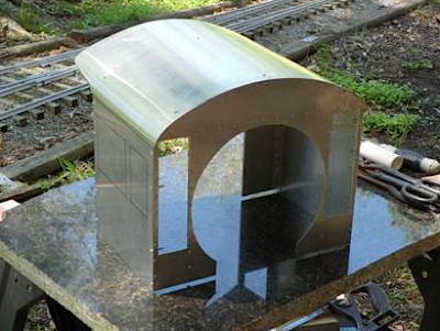
Cab
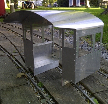
After cutting the boiler and window/door openings in the cab front and rear, I can definitely say I don't like cutting sheet aluminum! I used 20-gauge material and cut the openings with a jig saw. Screws (2-56) hold a variety of stiffeners, from 1/8 x 1/2" bar stock to 1/2" angle to 3/16" and 1/4" square tubing. I laid out the pieces with very careful measurements and marked the aluminum with a Sharpie pen. It was very surprising that the front and rear of the cab roof lines matched; even when I turned one around, both were the same contour ... a first for me!
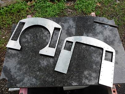
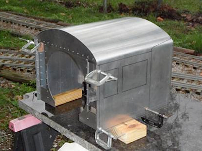
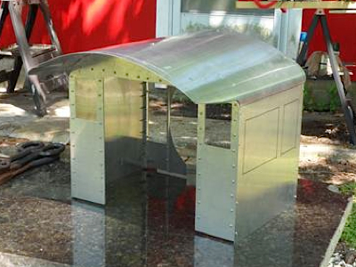
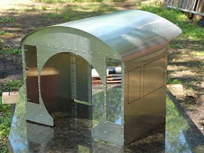
After I marked the sheet metal for the cab sides and roof, I clamped some PVC tubing to the slab of granite I was using as a workbench and bent the roof for the curves on each side. That turned out to be a benefit later. Before I cut the final roof shape, the photo shows that I clamped the roof/sides to the front/rear to be sure my bends were correct. I also did this to be sure the bend on the edges of the roof overhang would come out right.
I used tin snips to cut the excess roof/side material, but have yet to get the jigsaw out again to cut the side windows. Most of the 2-56 screws holding the cab together are in place, but I have a few holes left to drill. Bending the roof/sides BEFORE I cut the overhang turned out to be a good idea. The slight curve to the overhang came out very nicely. I am very happy with the cab.
Test Assembly
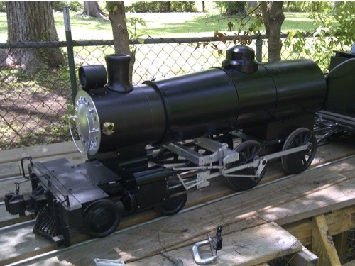
Time to test-assemble #260. It's not perfectly level on the frame, but it has the look! The steam dome is PVC cut to represent the proper size. The bell is from Cannonball, LTD., and the stack and door dogs are from Railroad Warehouse. None of the parts are attached, but they look just fine sitting in their approximate locations.
Obviously, the cab is crooked and not mounted, but even with those clear, unpainted and unfinished cylinders, it is coming along. Interestingly, the PVC boiler is so heavy, it makes the frame settle down on the driver and pilot truck springs far enough that the pilot scrapes the crossing boards. Eventually, I will have to raise the pilot and cylinders.
Over the last two weekends, I got back to it and did a few jobs that I had procrastinated on. First, I moved the pilot back on the frame. It was about two inches too far forward. I cut out two inches of the frame and re-drilled the mounting holes. I also strengthened it with more robust pieces of steel. Second, I put the cylinder wrapper on, and third, installed the running boards. All three tasks turned out easier than I thought. The pilot beam was originally bolted into a 1/2 x 1/2" piece of square tubing that spanned the two frame pieces. The tubing was connected to the frame with one 10-24 bolt on each side and the pilot was shaky, to put it mildly. Now it is connected to the frame, the pilot deck (1/8 x 2 x 12" steel), and a piece of 1" angle, also steel. For the cylinder wrapper I used .010" brass, with 4-40 screws to hold it on. The running boards are 1/8"-thick aluminum screwed to 1/4" aluminum rod. Sorry I don't have new photos, but by the time I finished putting the running boards on last night, it was dark. But in the fading light, I stepped back to look at the engine. The shorter pilot, along with the wrapper and running boards sure do make a difference in capturing the essence of the real loco. The light at the end of this tunnel is coming: air compressor and tanks, piping, hand rails, domes, marker lights, bell and head light are all that remain for the boiler. I still have to cut the cab side windows, but the cab is already cut to fit the boiler and looks great with the other parts in place.
Dec 2012
The cylinders are clear sheet PVC, with plumbing fittings representing the caps, and 5/16" bolts representing piston rods. The cylinder wrapper is .010" brass, bolted in place with 4-40 x 1/4" bolts. Obviously, when I paint the assembly, it will look much more cylinder-like. If you compare this view to a similar photo from several months ago, you can also see how I shortened the frame at the front. To me, this looks much better.
Right now, the boiler is sitting on the cylinder saddle at the front, and on a piece of 2x4 over the rear frame. I have the smoke stack mounted with four screws that are not yet tight – it still needs some work on the grinder.
The running boards are each made from one piece of 1/8 x 2" aluminum bar stock, about 22" long, and one piece of 1/8 x 1/2 " stock nearly 13" long. This represents a notch in the running boards on the prototype. I drilled 1/4" holes through the boiler and laboriously managed to get 1/4" aluminum rods all the way through to hold the boards. The boards are attached to the support rods with 4-40 x 3/8" hex bolts, although I plan to swap these for flat-head screws eventually.
Dec 2012
Dec 2012
Assembly
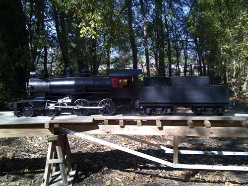
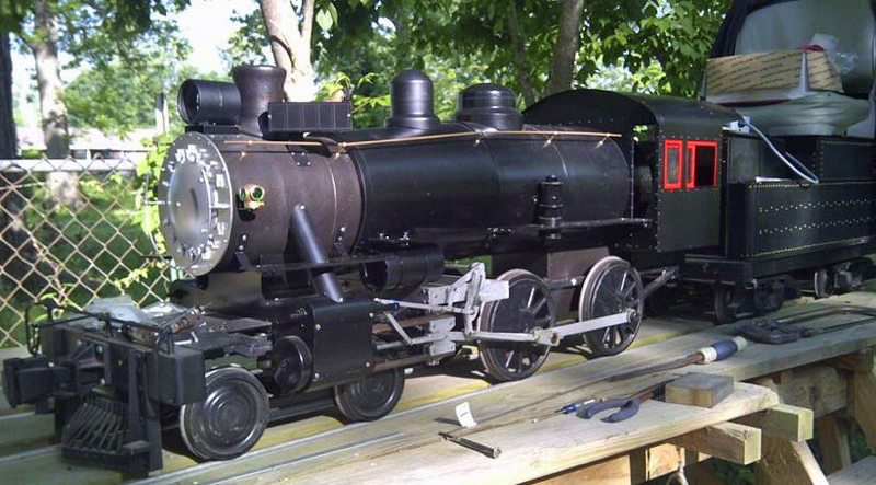
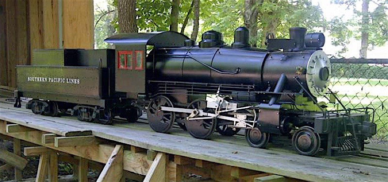
SP 260 (the 1/8 scale version) now has its first coat of paint! The boiler is coated with Rustoleum semi-gloss black and the fire box and smoke box are coated with a Rustoleum metallic graphite-toned color. I also painted the cylinders and cylinder wrappers, bell bracket, steam dome, running boards, back head, air pump, smoke box front, headlight and stack.
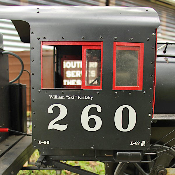
The cab is also coming along. The arm rests are on and I have built the brackets that hold the cab to the running boards. I need to complete the windows (so I can add that little splash of red paint), then I will paint the cab, too. All the handrail stanchion holes are drilled, as are the stanchions themselves The only parts I have yet to create are the sand dome, air tanks, and boiler fittings.
Jul 2013
Jul 2013
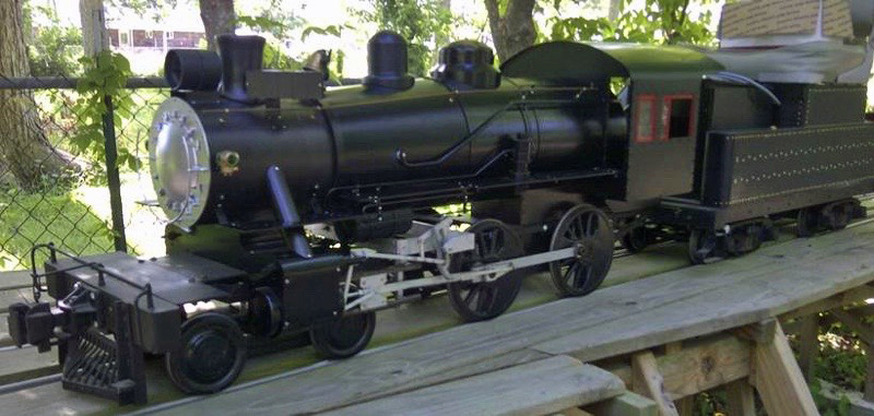
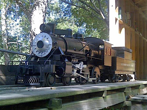
SP 260 is getting closer and closer to being finished. I put the hand rail stanchions and hand rails on the boiler, added the class lights and bell, and installed the air pump. I reapplied the newly-painted running boards, back head and smoke box front. My next task is to complete the cab, including the windows and doors, hopefully next weekend.
Jul 2013
Later, with the rain stopped and the temperature below 90, I could not resist adding the cab to SP 260. I took the seat off, too, for the photos. I still have lots of detail parts to add, but it seems to capture the essence of SP 260.
Jul 2013
Jul 2013
Jul 2013
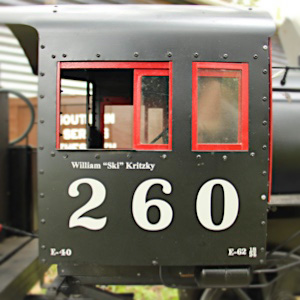
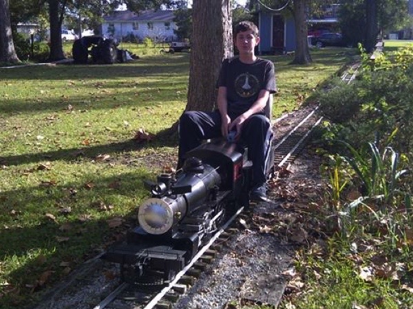
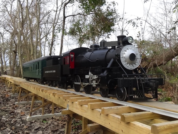
I finished the number boards for SP 260 and painted and installed them this weekend. The model still has lots of work remaining, but it is looking more and more like the real loco. The sand dome I made is not finished, so if it looks too tall, it is: I plan to cut it down about 1/2" and put a lid on it. And for those of you who wonder how a steamer can run without pipes to deliver steam to the cylinders, don't worry. It's electric! My kids and I took the chance to ride a little on a beautiful December 1st -– 65 degrees and clear blue skies.
Dec 2013
Dec 2013
Dec 2013
I spent another couple of easy-going hours Sunday making the steam delivery pipes for the cylinders. It took lots of filing the pieces of PVC to get the curves for the boiler and cylinder tops even close…I have an immense respect for those who make parts like this from metal! When I look at this photo, I think, the end is in sight. Then I think of all the air tanks, air and steam lines, the sand dome, and cab parts! I did receive the loco lettering, so a coat of paint on the tender may allow me to place "Southern Pacific Lines," but I don't want to get ahead of myself. When I put the lettering up to the tender and the cab, it was jaw-dropping. This baby is going to be a showpiece.
Apr 2014
SP 260 is slowly taking shape again. I can't believe I started building this loco over three years ago. Somehow, I got the running gear done relatively quickly, with the major superstructure items following within a year. Work slowed at that point, with the cab and a few detail parts over another two years. When I started building TNO Combine 467, all progress on SP 260 stopped for several months.
After last weekend's addition of the steam delivery pipes, I was able to add the smoke box running boards. I used 1/16 x ½" aluminum for the support brackets and 1/8 x 2" aluminum for the running board. The running board on each side also has a piece of 1/8 x 3/4" aluminum to give it the proper overall width. The new running boards are a bit flimsy feeling, so I will look into a way of firming them up.
Apr 2014
Mar 2014
May 2014
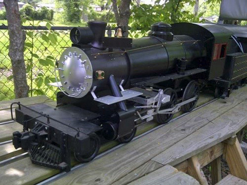
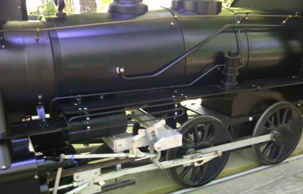
I added the air reservoirs and their brackets under the running boards of both sides. The tanks are pieces of 2" PVC pipe with knockout plugs in the ends. I used 2-56 x 1/4" brass screws to hold the plugs in place – by not gluing them, I can take them off if needed. The single-phase air compressor is made from two different O.D.'s of 1/2" I.D. washers for the lower section, and from a PVC fitting and washers for the top. A 1/2" x 5" bolt runs through the center of the compressor to hold everything together. I added a 1/2 x 1/16" aluminum bracket to hold the compressor to the boiler.
May 2014
Here, I added the air lines from the compressor to the reservoir tank, the steam supply line from the cab to the compressor, and the steam exhaust line from the compressor to the cylinder saddle. I also added the injector piping, although I still need to make a decent-looking check valve. If you look closely and compare these first two photos, you can also see that I cut down the height of the sand dome. My domes are not perfect, being made from PVC pipe fittings, but I think they are reasonable.
May 2014
Unfortunately, this shot is a bit soft on focus, but you can see the details of how I mounted the air lines to the brackets. The air and steam lines are 1/8" brass rod while the injector line is aluminum. This presents an interesting challenge. I understand that brass and aluminum don't like each other, electrically. Because all my brackets are aluminum, I painted them and the brass rods before I assembled everything. My hope is that the paint will help insulate the parts. I will study the drawings and photos more, but I think the only parts left for the Fireman's side are the two sanding lines. Next weekend: the Engineer's side!
May 2014
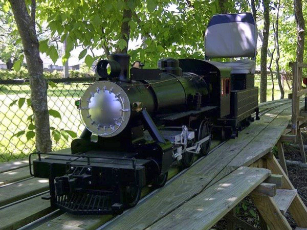
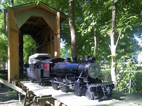
Here she is, popping out of the LT&P locomotive shed. I attached my version of the sand dome with two small screws. I also got the front steps made and installed. This is my only conscious departure from the prototype: the real loco has very robust brackets holding the running boards around the cylinder pipes. I added small brackets to the main running boards, and two more from the new step to the front deck on the pilot. Where these running boards were originally quite flimsy, the additional brackets make them quite sturdy. You can also see the newly-installed brake line (the glad hand was installed post-photo).
May 2014
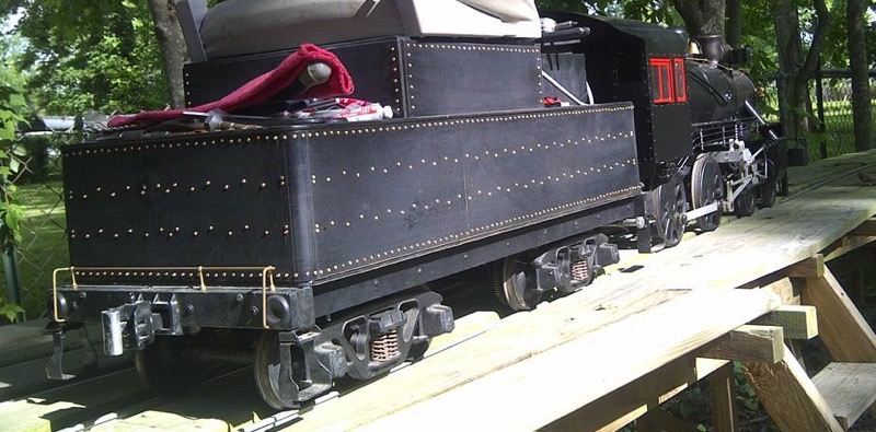
The coupler release bar is in place on the tender, although I still have to add the little lever for the release pin. Unfortunately, the tool box, water fill extension and the ladder don't exist yet. You can also see the new piping on the engineer's side of the loco, including the injector piping. After I took this photo, I added one more pipe – the steam supply line for passenger cars. The four pipe runs look very complex – this is one of my favorite tasks. I don't know if I like installing piping because of the complex look it gives a model, or because it tends to be one of the final tasks in building model!
For anyone who wonders how the loco is powered, you can see the gear on the second axle of the tender. Both axles on the front truck are driven. The loco has proven it can pull itself and the passenger car (and two people) up the railroad's only grade. SP ran the real 260 for several years on the Gonzales, Texas, branch, pulling one 60-foot combine and up to about ten or 12 freight cars (according to photos in Joe Dale's TNO book) on two round trips per day, with arrivals in Harwood scheduled to meet the east or west-bound Argonaut. I bet the ride cost a buck or so - wouldn't we just faint if we had the chance to ride two 12-mile round trips per day behind #260 for a buck each way?
Tender
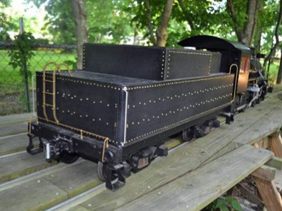
The ladder is brass, with 1/16 x 1/4" bar stock for the sides and 1/8" tubing for the rungs. It was interesting to bend the brass stock this way, and especially time-consuming to match both sides. I drilled and tapped the tubing for 4-40 screws, then used Lock-tite to solidify the ladder. The front grab iron is 1/8" brass rod, another case of discovering the difficulty of matching the two sides. The stanchions for the coupler release bar are the same type I used on the boiler.
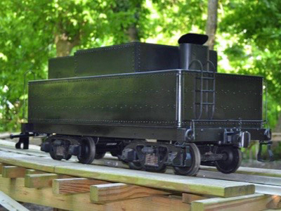
I procrastinated in building the water fill hatch. When it hit me that I could wrap thin aluminum around PVC pipe fittings to get the shape, it only took about two hours to create it. The top opens on a pair of hinges.
Jun 2014
Jun 2014
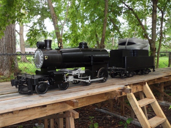
I have not seen any photos of the front of the tender. I assume some sort of steps or grabs let the fireman get up on top. Until I find out, I will leave this item unfinished. I made an oil hatch from a small piece of PVC and the aluminum cap to the icing from a can of cinnamon rolls. After the paint dries for a week, I plan to add the "SOUTHERN PACIFIC LINES" lettering to the sides, and the "260" and "5000 GALS" to the rear end.
Jun 2014
Jun 2014
Oct 2014
Feb 2016
Tom Bee
Our Southern Pacific #260 was featured on the website for Tom Bee's scale riding parts!
Most of you know me as a supplier to this great hobby of ours. I have been supplying fine trucks and couplers to the hobby of large scale railroading for over 25 years. I put my heart and soul into it. I plan on continuing to serve the hobby for many years to come. I am not downsizing or retiring in any way, shape or form. In fact, I am expanding.
Tom Bee
 Snapshots
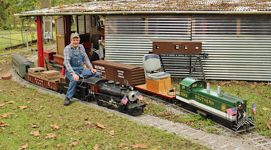
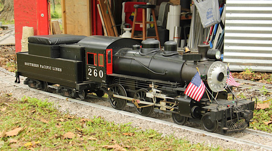
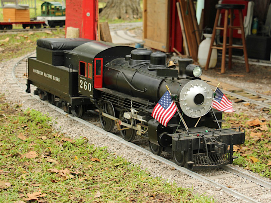
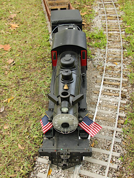
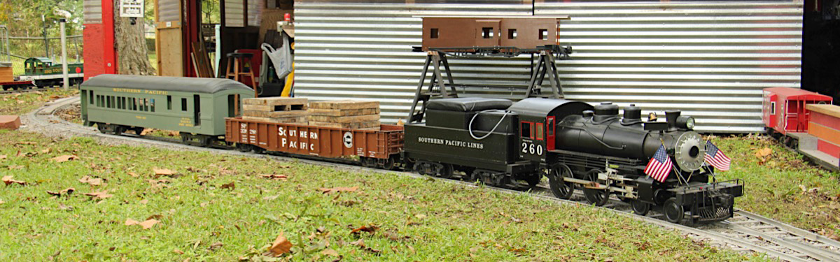
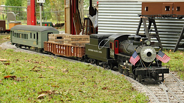
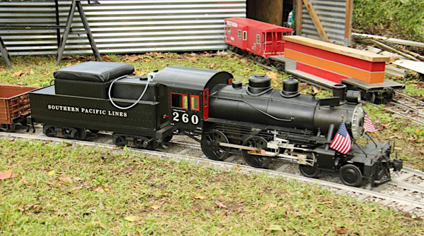
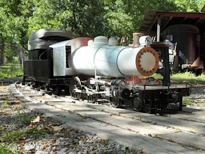
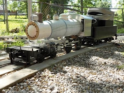
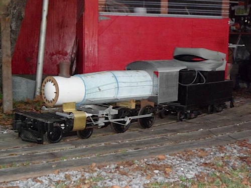
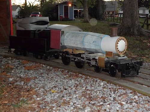
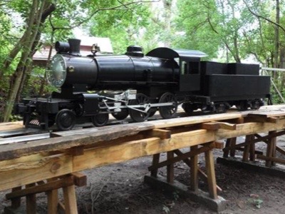
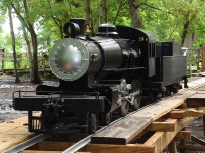
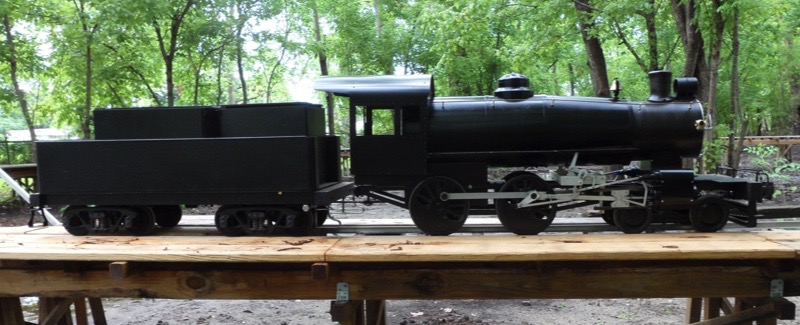
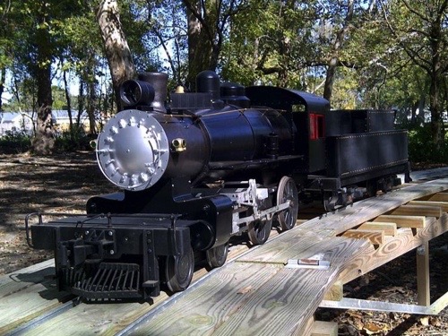
Nov 2018 / RWH
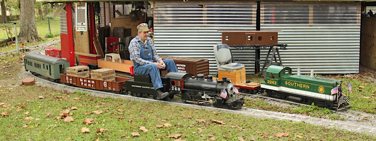
Nov 2018 / RWH
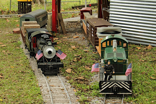
Nov 2018 / RWH
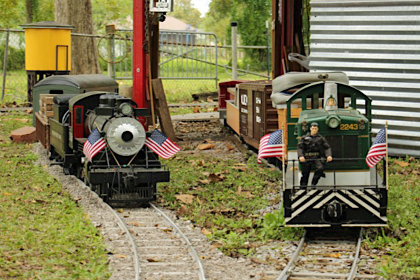
Nov 2018 / RWH
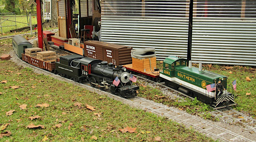
Nov 2018 / RWH
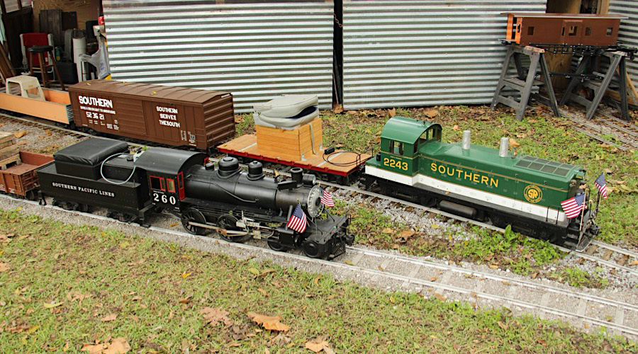
Nov 2018 / RWH
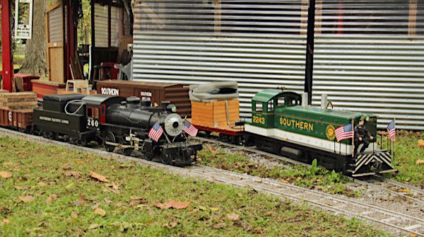
Nov 2018 / RWH
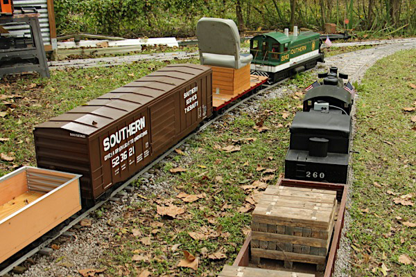
Nov 2018 / RWH
Nov 2018 / RWH
Sources
Like the Southern NW-2 model, this steamer project includes parts from several different manufacturers:
- Plum Cove Studios - arch Bar trucks, electric tender drive, motorized wheel sets, and control system
- Precision Steel Car Co. - bearing blocks and tender bolsters
- Real Trains - handrail stanchions
- Tom Bee - drivers (under contract to Santa Clause) and pilot wheels
- Cannonball, LTD. - couplers, tender coupler pocket, bell
- Connie Miracle - vinyl lettering
- Railroad Warehouse - smokebox front, stack, and other detail parts
- Godshall Machine Works provided the Andrews trucks
- Charlie Lorentz welded the loco and pilot truck frames
- Lowe's - frame stock, washers, large bolts, etc.