 |
Louisiana, Texas & Pacific Railroad Outdoor Division Mainline |
mainline tour / Nov 2018 / RWH
Overview
2017 mainline map
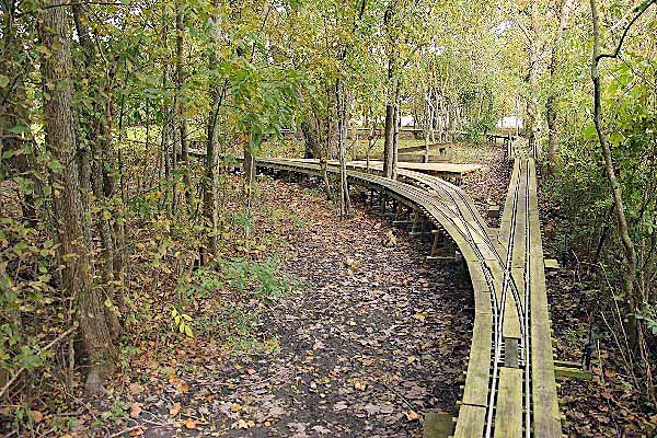
South Loop
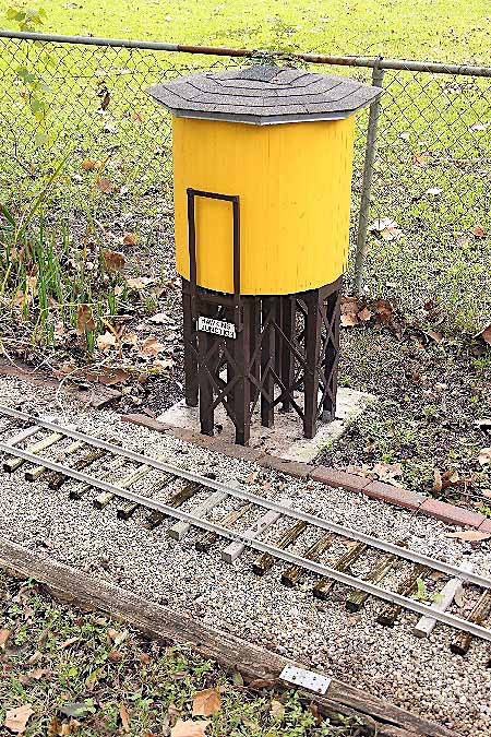
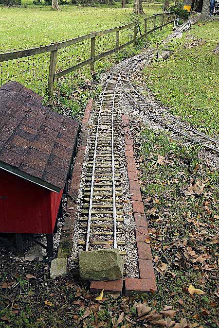
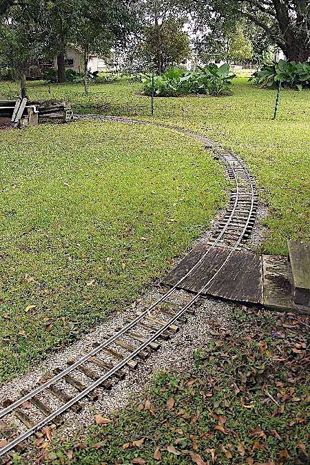
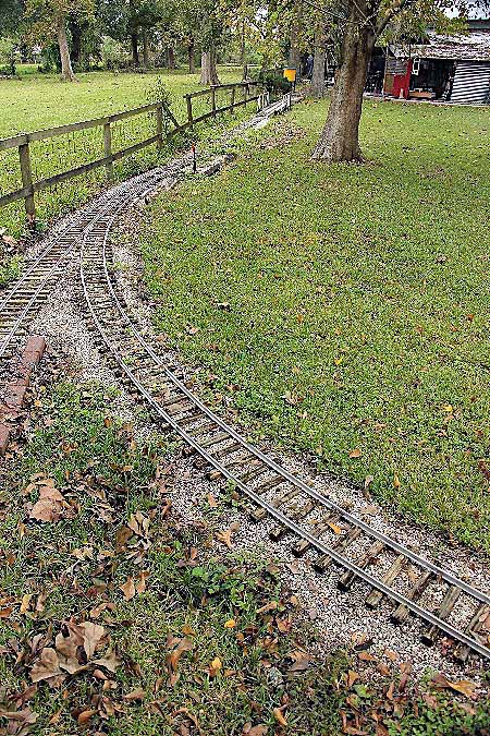
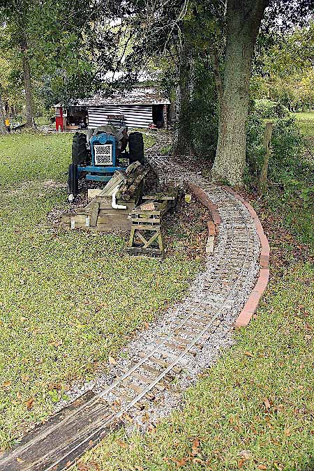
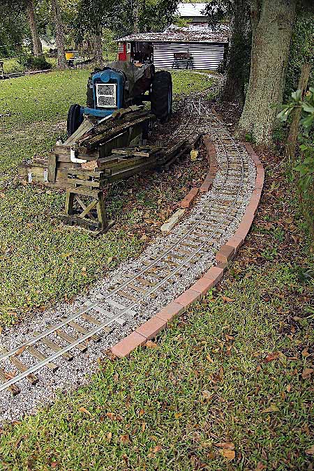
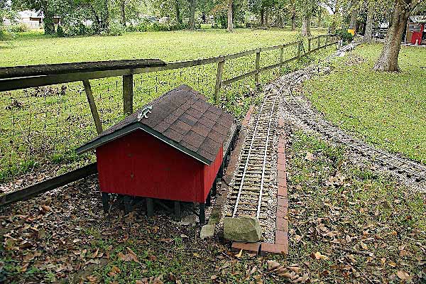
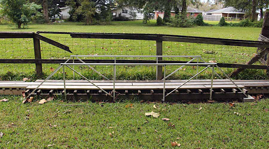
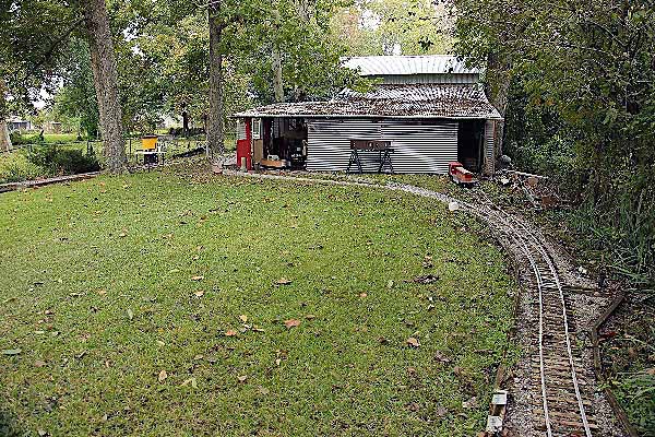
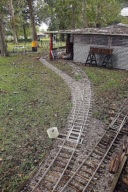
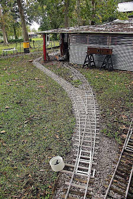
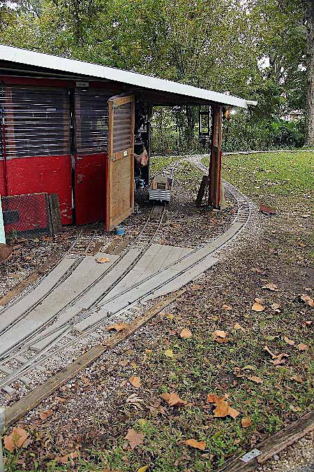
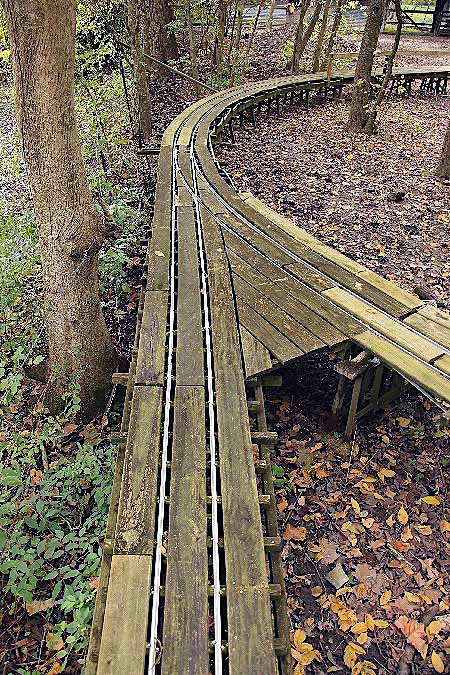
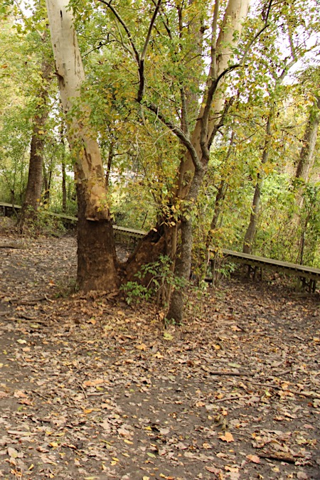
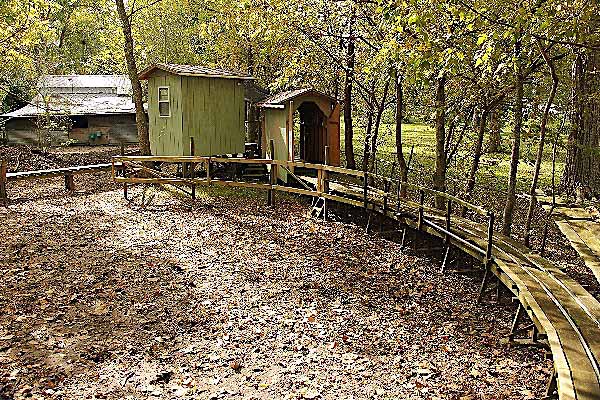
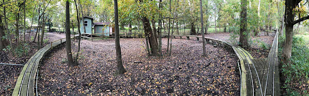
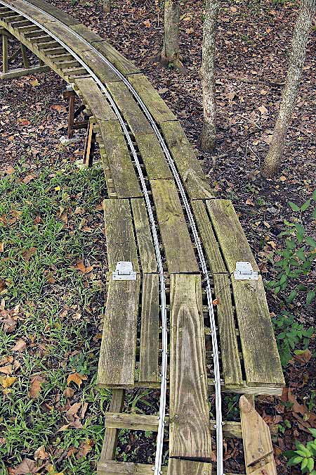
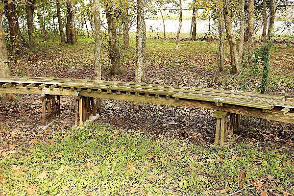
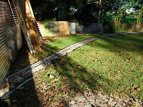
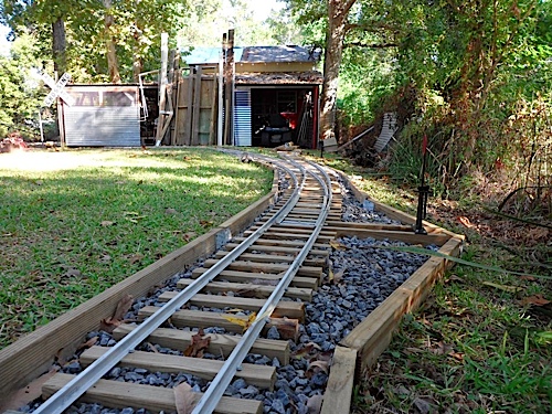
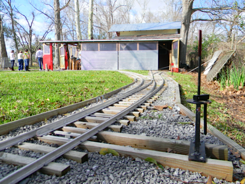
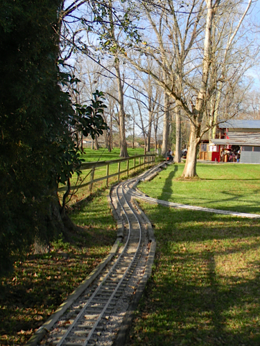
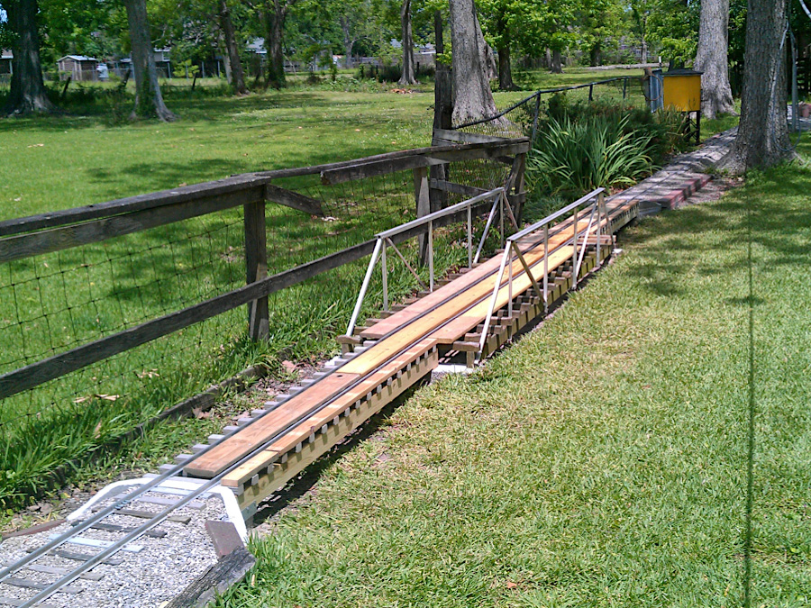
The South Loop of the Lousiana, Texas & Pacific Outdoor Division mainline begins at the switch at Hawkins Junction, passes the water tank, crosses an aluminum truss bridge over a portion of lawn, includes a turnout for the A. P. Price Supply siding, curves around at a 25' radius, includes a second turnout for the loading ramp siding, and ends in the area around the barn with the first of two passing sidings on the railroad.
Nov 2018 / RWH
Nov 2018 / RWH
Nov 2018 / RWH
Nov 2018 / RWH
Hawkins Junction storage area
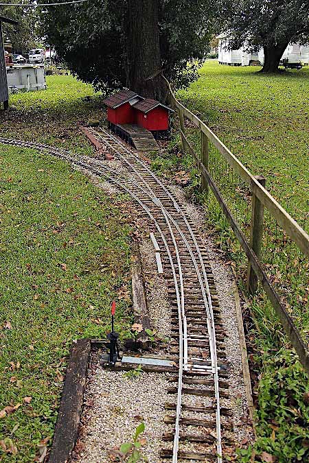
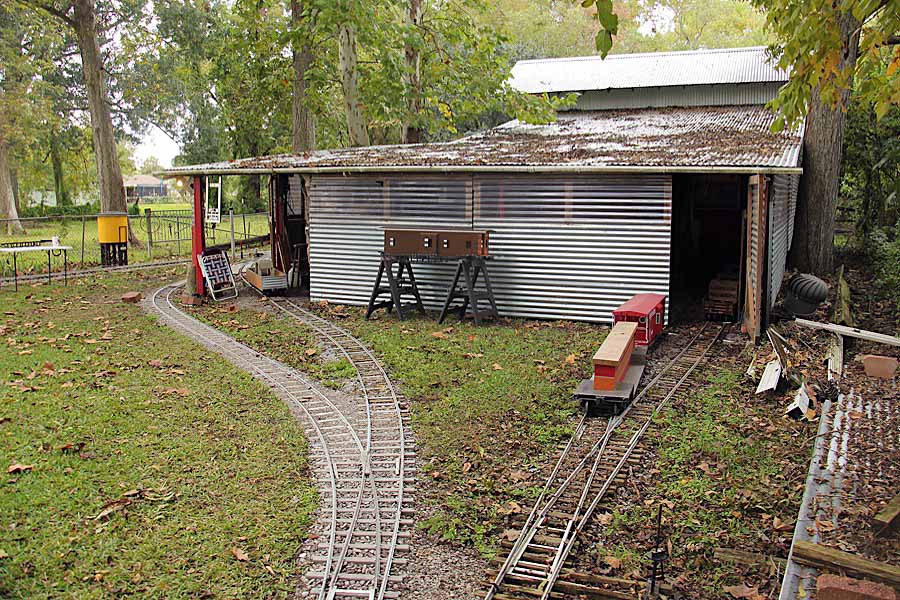
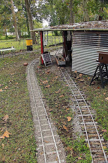
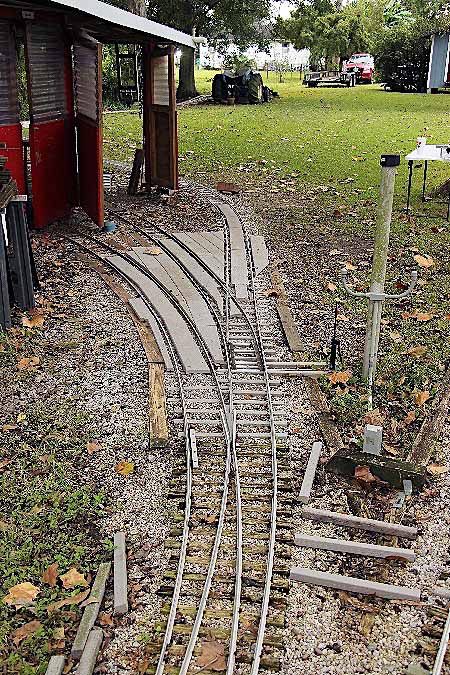
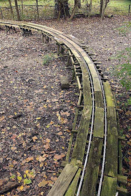
The storage area around the Hawkins Junction switch includes a turnout to two sidings that lead to a storage area for rolling stock inside the barn. A third storage siding connects to the mainline near the north end of the South Loop passing siding. By these these three sidings, the barn provides storage for all of the Outdoor Division's rolling stock, freight and passenger.
Nov 2018 / RWH
Nov 2018 / RWH
Middle Loop
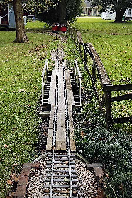
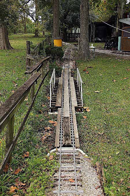
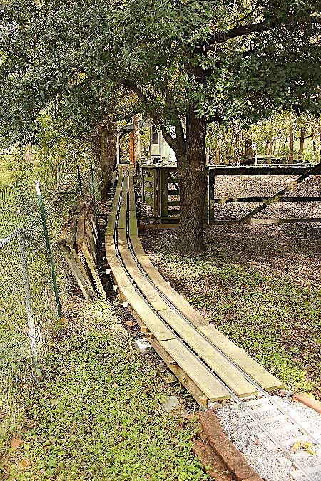
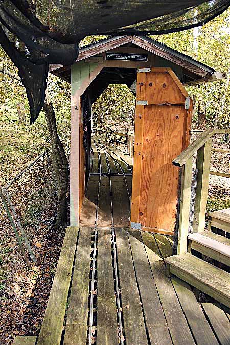
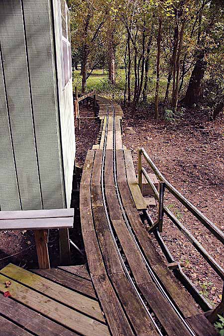
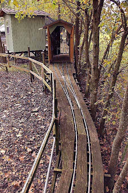
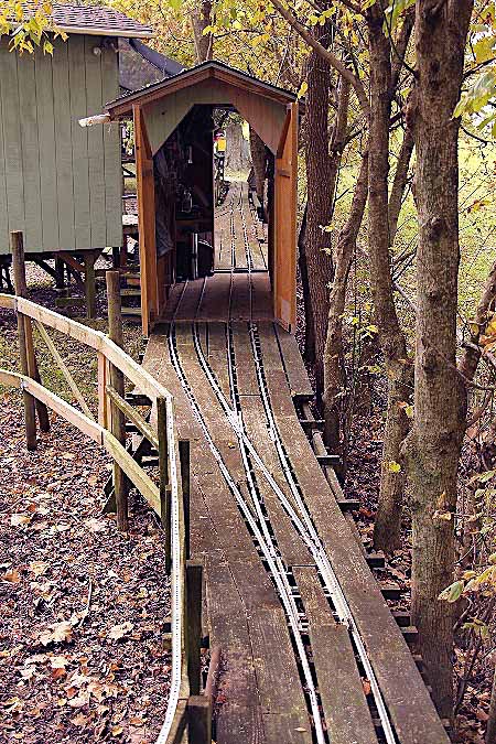
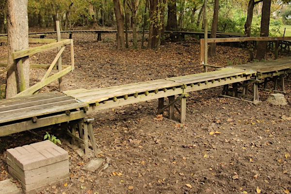
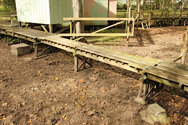
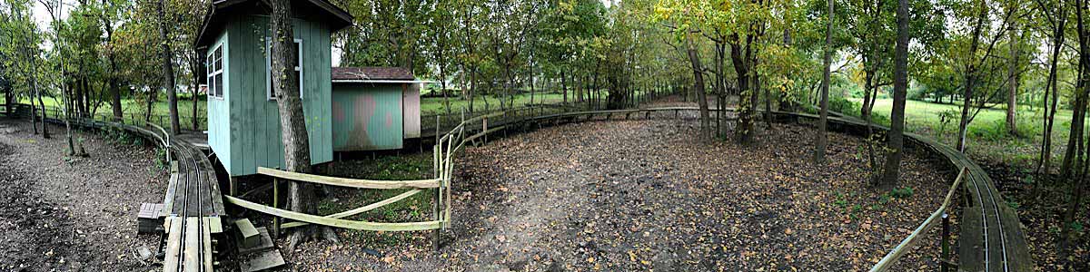
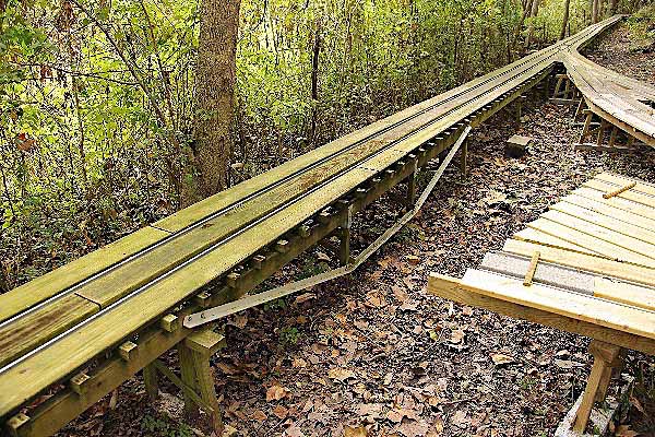
The Middle Loop of the Outdoor Division was the northernmost portion of the mainline until the construction of the current North Loop extension, below. The Middle Loop begins at the north end of the Hawkins Junction switch, climbs up the railroad's steepest grade to begin the raised-deck portion of the mainline, includes the two-track locomotive storage shed and the future Dispatcher's Office, and sweeps around in a 25' radius loop over two sections of lift spans which allow passage for the horses on the property.

Nov 2018 / RWH
Nov 2018 / RWH
Nov 2018 / RWH
Nov 2018 / RWH
Nov 2018 / RWH
North Loop
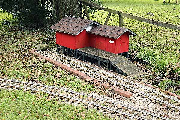
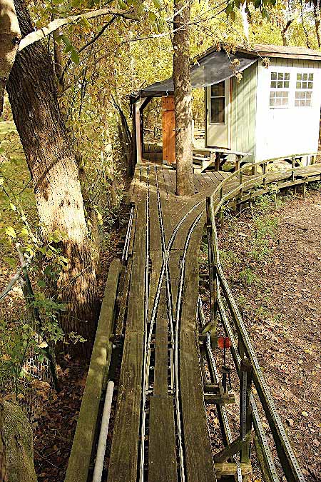
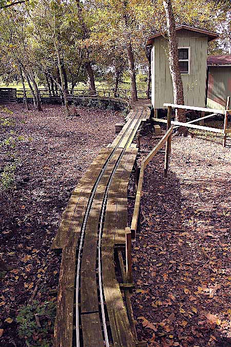
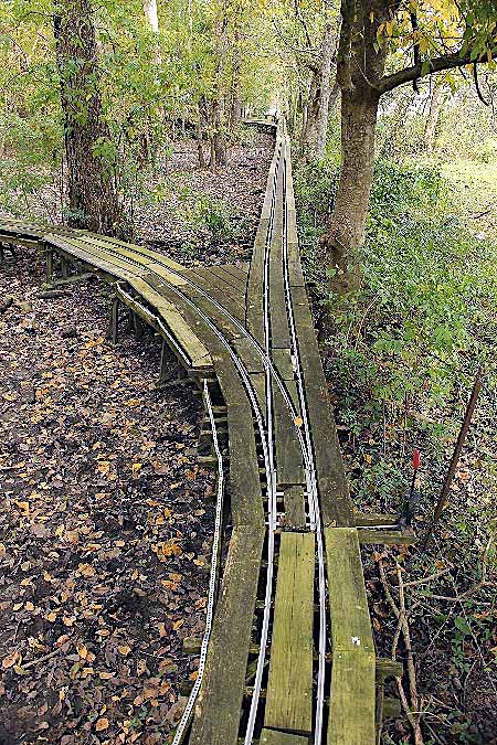
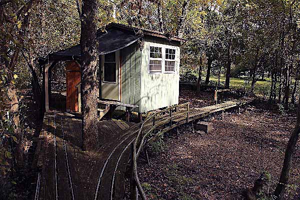
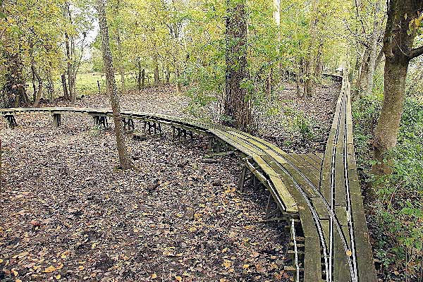
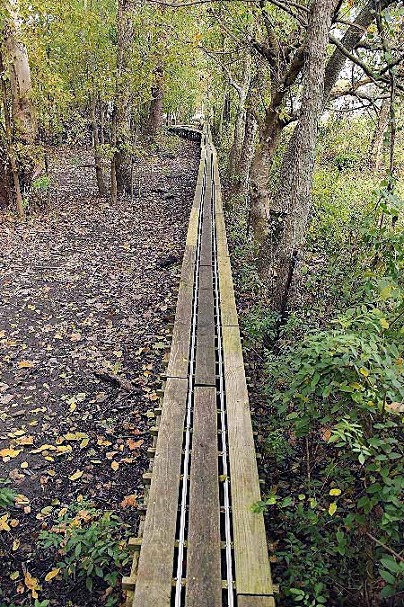
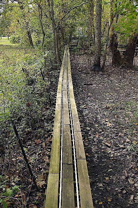
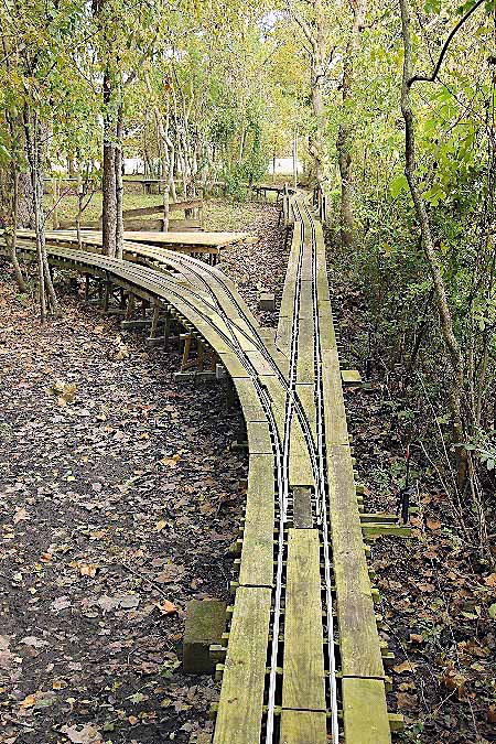
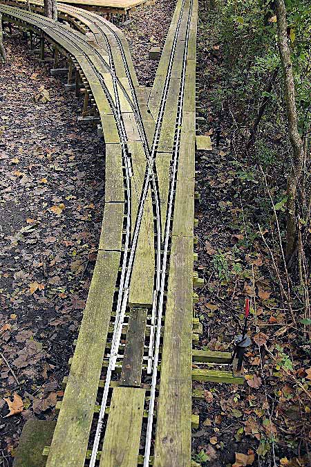
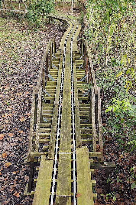
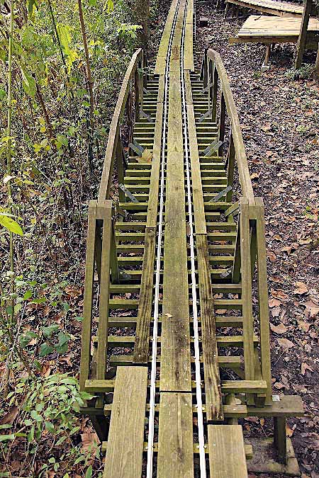
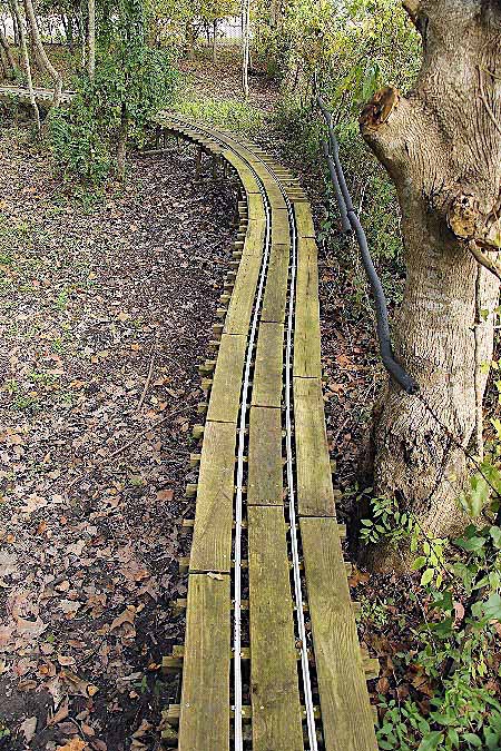
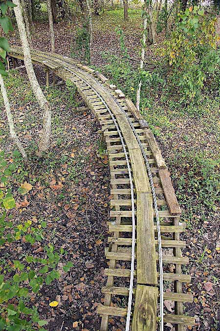
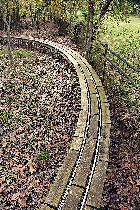
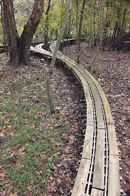
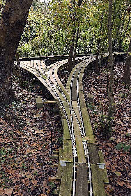
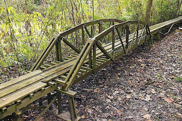
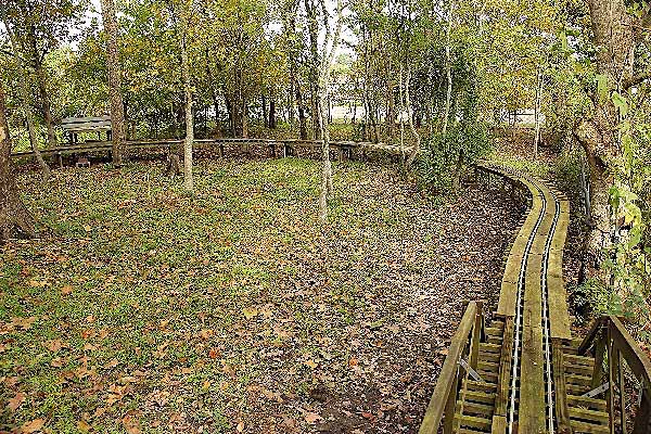
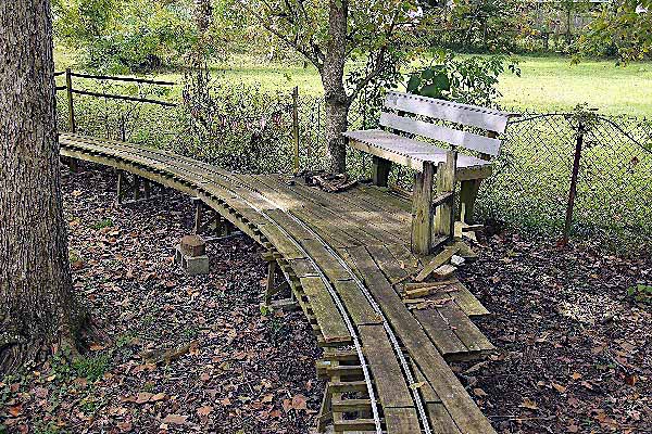
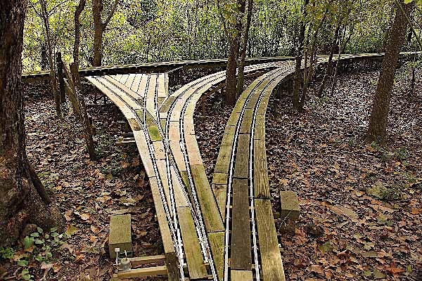
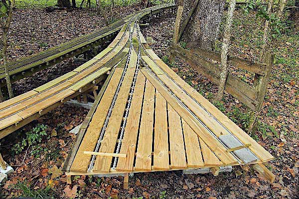
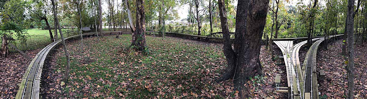
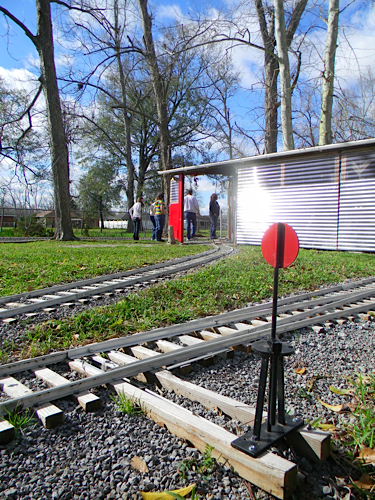
The North Loop of the Outdoor Division is the newest portion of the mainline. It begins at a turnout off of the Middle Loop and proceeds north along the railroad's longest tangent to a second turnout that begins the loop. The North Loop itself is likewise a 25' radius curve and includes a raised wooden truss bridge section, a subsequent lift span section, a small passenger platform with a sitting bench, the second of two passing sidings on the railroad, and a two-track switching area for shunting and storing rolling stock. A working signal system protects trains in the North and South loops from entering the single-track tangent section if that block is occupied by another train.
Nov 2018 / RWH

Nov 2018 / RWH
Nov 2018 / RWH
Nov 2018 / RWH
Nov 2018 / RWH
Construction Notes
Spring 2010
LT&P system map / 2012
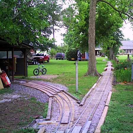
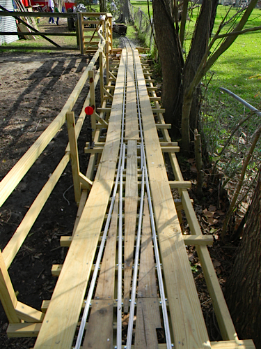
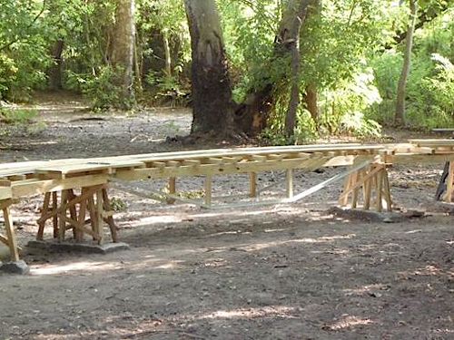
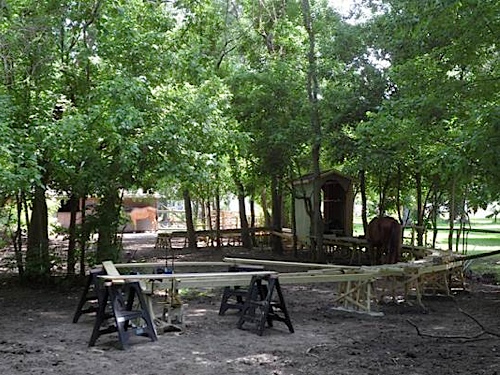
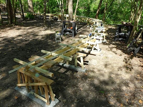
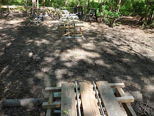
I have been building the riding railroad for over a year. The gauge is 7.5 inches. About 250 feet of track is in place, with two operating switches and one not yet completed. In building the mainline, I attached the ties to eight-foot stringers for stability on our soft ground, then built a grade from sand. I put weed barrier on the sand, then placed the tie/stringer panels on that and screwed the rail to every other tie. I finished it with #3 limestone ballast. So far, 250 feet of track has required almost 100 eight-foot 2 x 4s, 1500 track screws, four yards of sand, four tons of limestone and 500 feet of rail. The railroad is planned to be about 600 feet long with return loops at each end. I plan to operate with a dispatcher and should be able to run three trains at one time, provided I have that many friends with riding trains!
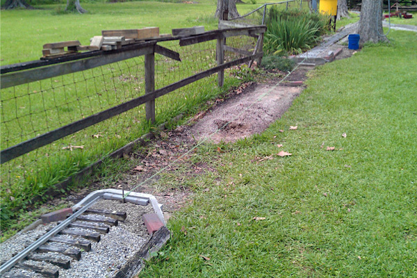
southbound view of mainline / Apr 2010
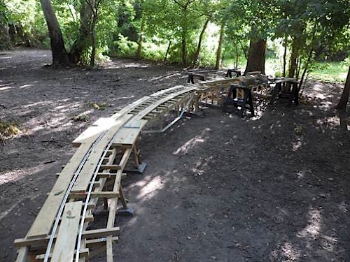
northbound view of storage and mainline / Apr 2010
southbound view of new mainline switch / Jun 2010
northbound view of new mainline switch / Jun 2010
 South Switch
 The first concept for turning locomotives for the south end of the Louisiana, Texas & Pacific Railroad was to use a wye. The first switch for this wye was installed in the main line, but was never completed. Later, LT&P engineers rethought the operational possibilities of a wye as compared to a return loop. The loop would allow operators to run continuously, even if it was slowly and carefully due to its 25-foot radius. The new plan includes the loop and a loading ramp for visitors. For a 25-foot radius curve to fit on the property, the new switch had to be moved closer to the fence. This required a new, curved switch. The plan also included a revision of the grade near the switch to make the transition smoother.
The grade is made of sand, with a weed barrier, and ballast on top. Track crews lifted out the original switch quite easily. Almost all of the original ballast was reclaimed, too. The revised grade used some new sand to supplement the original. In all, about 30 feet of the original track was removed.
The new switch ties were laid out and stringers were screwed to the bottom of the ties. (Yes, this operation was done with the ties upside-down.) Track crews turned the panel over and placed it in its location. The crew added new rails, starting with the outside running rail for the 40-foot radius, then adding the inside running rail for the 25-foot radius.
northbound view of new south switch / Jun 2010
southbound view of new south switch / Jun 2010
With the running rails in place, the track crew added the frog and switch rails to fit. They placed the points in their spots to determine the start of the switch rails. Once they got the frog location figured out, they notched the rails for the bend near the frog, then used track gauges to screw the rails in the correct places. Some LT&P rail was delivered in 8' 10" sections and some was delivered in ten-foot sections, all from Real Trains. The track gauges were from Cannonball Ltd.
The crew notched the points to fit the running rails with a Dremel tool, cutting disks and a heavy file. They installed the points with regular track joiner screws (10-24 x ¾" hex head with nylon lock nuts). The crew also added new landscape timbers and ballast. On the LT&P, most of the ties are screwed to stringers. This means that the rails can be screwed to every other tie. The LT&P uses typical one-inch hex-head screws to hold the rails in place.
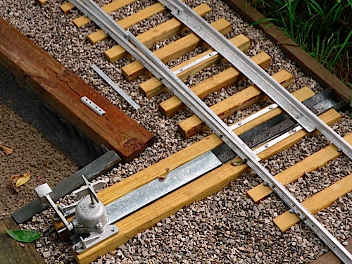
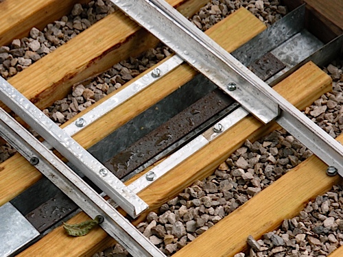
The Cannonball Ltd. RTR Loco Switch Machine includes the assembled body, direction indicator, throw bar and link bar. LT&P track crews had to drill (3/16") the link bar and the points (made from 1/8 x ¾" aluminum angle), then bolt them on with 10-24 x ¾" hex head rail joiner screws and nylon lock nuts. Shims of 1/8 x ½" aluminum support the points and keep them at the proper height to line up with the top of the Real Trains rail. This also lets the points slide all the way over to the rail head without hitting the foot of the rail. Crews mentioned the intense amount of work involved in grinding and filing the points to fit the head of the rail!
Where the points contact the running rails, crews had to drill the foot of the running rails to accept 1 ¼" galvanized wood screws. Regular hex head screws were used in all other locations where they would fit without disrupting the points. Some builders also drill the foot of the running rails opposite the frogs to attach them to the ties. This lets them fit the guard rails close enough to the running rails to keep the flanges from picking the frog.
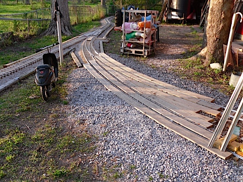
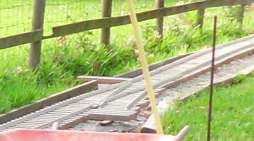
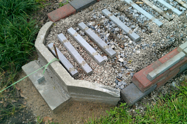
The descending grade from the bridges is much smoother than the original. The photo also shows the switch guard rails: the 40' radius has a piece of regular rail, but the 25' radius curve has 1/8 x 1" angle stock. The outside guardrail is mostly for show, whereas the inside guard rail is functional to keep car flanges from picking the frog.
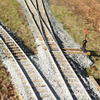
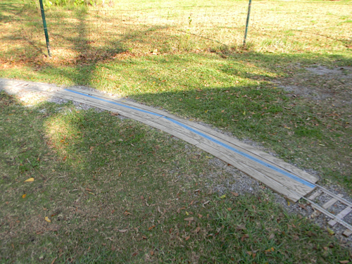
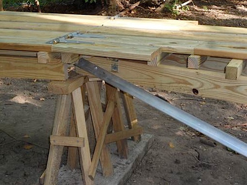
The return loop with its 25' radius curve will continue here. The piece of rebar stuck in the ground shows the approximate location of the curve's outside rail as it sweeps around the yard. The end of the grade coming from the bridges enters a short S curve. The new switch is about 16" closer to the fence, requiring the jog in the track. The S curve has a straight stretch of about 4 feet between its curved segments. This may cause binding in couplers of longer cars, but seems to work on the LT&P, where the longest car is about six feet. Keeping track level side-to-side is also very important. Cars track better on level track. With a 25' radius curve, level track is even more critical.

The completed switch took three weekends to build. The next project is to construct the grade and track for the remainder of the south return loop, then have fun running on it!
Fall 2010
The first return loop is almost done. Looking north towards the barn, you can see the cut I made across a hump in the yard. At its deepest point, the cut is 5 inches in depth. I did my best to keep the bottom of the cut level. Even so, it still has a slight crown to it, perhaps an inch or less above the grade approaching it from the curved switch at the bottom center of the photo, and maybe 1.5 to 2 inches from the track in the corner of the barn.
To the right, you can see a curved switch that will lead under the eaves of the barn. I plan to have two tracks there for storage, in the hope that all my rolling stock will fit! The switch has a 100 foot radius on the left side, with 40 foot radius on the right. My Southern Railway caboose is peeking out under the corner of the barn. To help protect it from the weather, I had put up a couple of pieces of old tin roofing. Just to the other side of the caboose is what I call Hawkins Junction, where the two legs of the loop join.
northbound view of first return loop / Oct 2010
northbound view of return loop cut / Oct 2010
As these photos (below) show, almost all the rail is in place around the loop, although I had only tightened the track screws on one rail. I still need to put the gauges on the rails and tighten the second rail. It also needs more ballast to fill in completely between the ties and on the sides of the cut up to ground level. I will have to run my riding lawn mower over the track here to store it in the barn. The white PVC pipe in the photo (right, below) is for drainage. I placed the two 1 inch pipes at the lowest point on the inside of the loop so water could drain to the ditch to the right. When I have the track adjusted, the grade to the hump will be very slight.
return loop trackage in place / Oct 2010
northbound view of barn turnout / Oct 2010
You can see the short gap in the rail in the foreground. I had added a piece of rail about 18" long to get the original track to stick out under the sliding door of the barn. I'll take that out, and add a new piece about 3 feet long to complete the loop. This whole curve is 40-foot radius. It's exciting to contemplate running all the way around.
northbound view of future storage spur / Oct 2010
northbound view of completed return loop / Oct 2010
The south return loop is now completed!
The curved switch leads to the mainline at Hawkins Junction to the left and to a pair of storage tracks to the right. This is the first switch with a 40-foot/100-foot radius curve. The points are three feet long: a foot longer than the points on all my other switches. I also installed a high-level switch stand from Gordon Briggs. The stand was complete with all the necessary links and was painted.
For the first time in two months, I was able to roll my caboose out from under the corner of the barn. All the rails are now properly gauged and screwed to every second tie (every one in some stretches). The caboose is sitting on the hump (right), the highest part of the railroad right now. Even though it is a hump, I cut out about five inches of dirt to minimize the grade. The grade you see comes up from Hawkins Junction and rises about four inches in 20 feet.
With the caboose on the south return loop main line at left, the diverging route heads towards the right-hand side of the barn. You can see the right-hand track switch panel that will lead to two storage tracks (above, right). Each will be about 18 feet long under the roof. The hump in the yard is lower here, but I will still have to cut about three inches of dirt from under the left side of the switch.
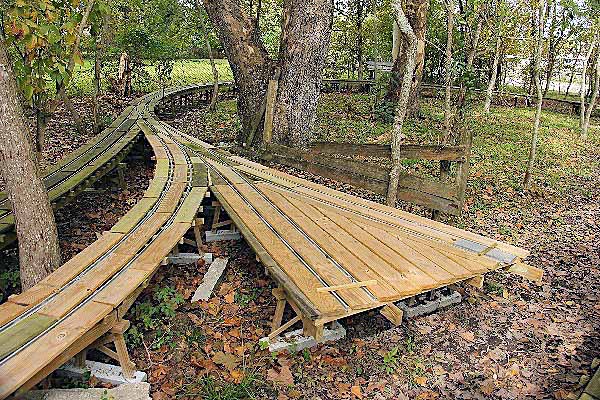
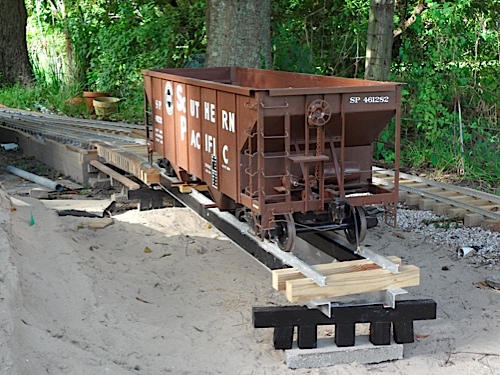
Loading Ramp
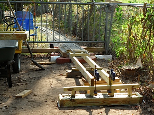
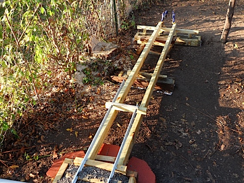
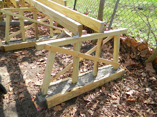
This project is an adjustable loading ramp to facilitate a visitor unloading a car or locomotive onto the railroad. The ramp is incomplete at this time, as I need to build a suitable support structure for the end of this span. I also plan to build one more span to allow a total rise of three feet. Each span is eight feet long, with hinges to allow them to be raised and lowered.
loading ramp / 2010
loading ramp / 2010

loading ramp / 2010
Winter 2011
LT&P system map / 2011
northbound view of installed shed spur / Jan 2011
Here you can see the finished curved switch and the new switch in its grade. You would not believe how many leaves were all over the tracks ... it took me at least half an hour just to blow most of them away. Then, as I put in more ballast, I was constantly digging leaves and pecans and pecan husks from the ballast. Can't allow all that organic material in there to retain water!
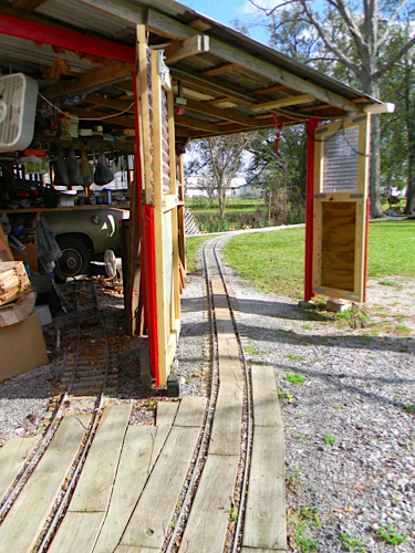
Switch points are labor-intensive. Filing the angle stock to fit against the rails takes an hour or so for each point. So, I have the switch completed but not yet useable. To avoid a roller-coaster profile to the storage track approaches, I had to dig the left side of the switch area out about 5 inches. Although the track still has a bit of a dip as it enters the shed, that will remain so I can slide the big door to the right if I ever get my old Barracuda out. I do plan to put hinged doors in place to protect the storage tracks and lawn equipment.
You can see that I have cut back on ties on the storage tracks. I figured that my light-weight rolling stock doesn't need heavy-duty track, since the track will not be ridden on. The two tracks will both go almost to the wall. My O scale train room is on the other side of the wall. The tracks will share the shed space with my go-cart and riding lawn mower. So, that was my latest weekend. Running my train will be much easier and convenient once this work is done.
installed storage tracks switch / Jan 2011
inside the storage shed / Jan 2011
UPDATE: The two new storage tracks under the barn roof are now complete. My son drove the first short train into the “engine house” Saturday. The my daughter did the first switching moves when we picked up the riding car from Hawkins Junction Sunday. We picked up the car, rode around the south loop, dropped the car, then manually moved it past the loco. Then she coupled to the car and backed up, I threw the switch, and she placed the car on the right-hand storage track. She then backed up again, I threw the switch, and she put the loco and hopper on the left-hand storage track for the night. Pretty neat!
completed storage tracks into barn / Feb 2011
rolling stock on new storage tracks / Feb 2011
loading ramp switch awaiting new ballast / Feb 2011
Fall 2011
Just before Thanksgiving 2011, the LT&P work crew (father and daughter) extended the north end of the main line by constructing an abutment for a new trestle. It includes red concrete garden-style blocks and a piece of 6" PVC to serve as a culvert. The crew had to revise about fifteen feet of the existing railroad to begin the transition grade to the new trestle. It took several loads of new ballast for the grade. This was one of the first parts of the LT&P to be built and is about three years old. All the ties were in good shape, but since most of the LT&P is built with the rails screwed to every other tie, the crew put screws in every tie on the revised grade.
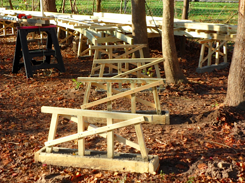
Since the LT&P is a small railroad with tight curves (at least for a riding railroad), it is not designed to carry two-ton locos. Two existing trestles carry trains by using four-foot spans of 2x4s. They are very solid. The new trestle will have a total of four 2x4s on each four-foot span.
The drawing shows the basic design, with a four-foot span of 2x4 stringers and an average rail height of just over two feet. The handrail on the LT&P trestle is intended to serve two purposes: first, it will help anyone on the trestle be safer in case of a problem during operation; second, it will keep the horses from trying to go over it!
northward extension work / Nov 2011
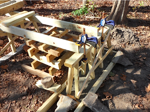
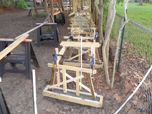
Once the abutment was done, with ties and the first pieces of rail in place to aid in lining things up, the crew added cribbing to support the first two stringers, then added the first two bents. One was a simple piece of 2x4 set in concrete cross-wise. The second bent is the trestle’s first real bent. Great care was taken to ensure the bents were level. The clamps on the bent are actually holding it in place as the concrete sets.
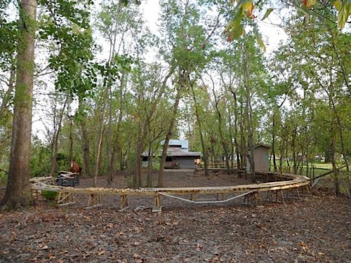
Within another 16 feet, the grade will reach the final height of the trestle and level off. The current plan is to extend the trestle for several hundred feet (depending on funding and time availability), with a return loop at the north end of the property.
Nov 2011
Nov 2011
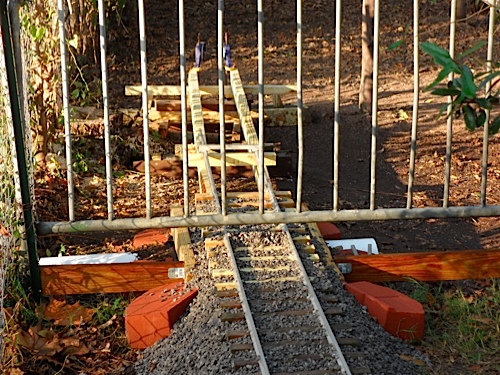
The barricade across the tracks is part of the original fence keeping the LT&P horses in the yard. A new gate will go here to replace the barricade to keep the LT&P dogs from going into the horse yard.
Jan 2012
Jan 2012
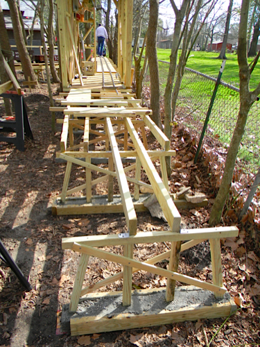
In the new year, work progresses northward. As you head north on the main line and ascend the new raised trestle, you reach a major switch. I have been working on the diverging route turning to the right (as seen in these pictures). My lovely daughter likes to help me and keep me company, and she was on hand for the photo below. She is sitting near the newest bent on the curve. This bent is very heavy duty, as I plan for it to support the end of a short drawbridge that will allow me to drive through the right of way if I need to. The trestle is pointing northeast at this point. The straight, 10-foot-long drawbridge will be next, then the trestle will turn left to make a loop all the way back to the other leg of the switch and thereby completing the north end of the mainline.
Jan 2012
Work has now begun on the new 4' x 10' engine shed located in the loop on the north end of the railroad. The lefhand shot below is looking north, while the righthand shot is looking northwest. A switch will be on the north side facing the shed; the main line will go straight through and the spur will be on the east side of the shed. This shed is 6'2" tall inside, so I can stand up without hitting my head. The shed is large enough to hold SP 260 (a 4-4-0) and SR 2243 (a Southern NW-2). I plan to make it critter-proof so that I don't have worries about the wiring and such.
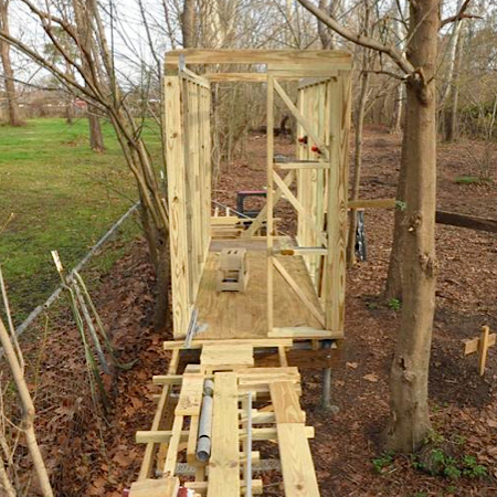
Feb 2012
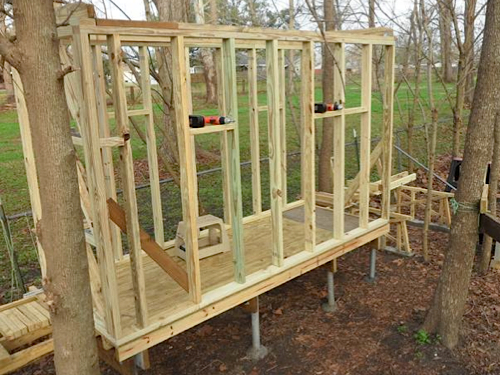
Feb 2012
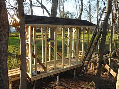
I took the above photos on Saturday. By the time I finished up on Sunday, I had the roof rafters in place and was close to having the eaves installed, ready for the plywood sheathing. If things work out, I hope to get the roof on this weekend and maybe get the main line rails laid.
February 2012

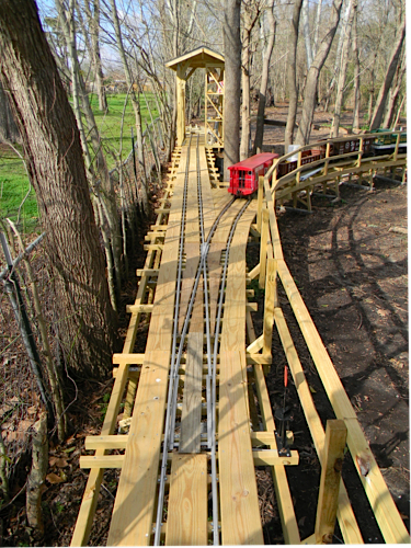
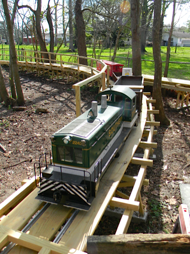
In February 2012 the Vice President of Web Page Operations of the Louisiana, Texas & Pacific made an inspection trip on the Outdoor Division with President and Trainmaster G. Payne. The inspection included various trips around the length of the existing mainline, behind both locomotives currently in operation. As of that visit, about two-thirds of the dogbone-shaped mainline is in place, with work underway on the raised portion of the line on the north end of the property. We operated trains for several hours on a sunny Sunday afternoon, including some switching operations as we rescued a dead NW2 switcher and put the rolling stock in the storage shed at the close of business. The mainline looks great, with curved turnouts, clean ballast, and a smooth S-curve snaking through the corner of the storage shed.
under construction / Feb 2012 / RWH
example pier structure / Feb 2012 / RWH
locomotive shed / Feb 2012 / RWH
Feb 2012 / RWH
looking northbound / Feb 2012 / RWH
looking southbound / Feb 2012 / RWH
mainline divergence for return loop / Feb 2012 / RWH
Feb 2012 / RWH
return loop through shed / Feb 2012 / RWH
storage yard lead / Feb 2012 / RWH
vehicle crossing / Feb 2012 / RWH
shed crossing / Feb 2012 / RWH
south end siding switch / Feb 2012 / RWH
south end siding / Feb 2012 / RWH
southern end of mainline / Feb 2012 / RWH
storage yard switchstand / Feb 2012 / RWH
Marrero, La / Feb 2012 / RWH
Spring 2012
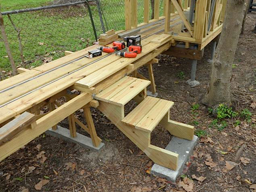
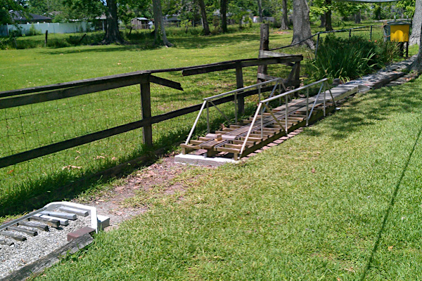
Spring time certainly puts demands on my outdoor time that is not focused on the riding railroad. With the mild weather of December 2011 and January 2012, I guess I installed a hundred feet of trestle, including the basic structure and roof for the locomotive shed in early February. From mid-February through March, I think I may have put in 16 feet of new trestle.The trestle is only two feet off the ground, but my 53-year-old legs do not like jumping off or climbing up, so I installed steps. Wow, what a difference.
Mar 2012
Mar 2012
Looking south (above, right), you can see the two newest piers of the mainline raised trestle. These piers are the beginning of the north return loop. On this side of the loco shed, I jogged the track closer to the fence in order to have the minimum 25-foot radius for the loop. Our three horses are in the background, watching. I still have more than half a circle to build. The switch you see will let me store both my locos in the shed. I have another storage area under the roof of my barn, with enough space for all my rolling stock, including the models I have parts for, but are not yet built. Wow! What a job this has been.
Apr 2012
Apr 2012
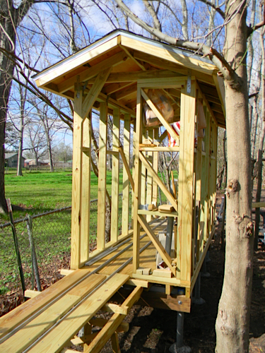
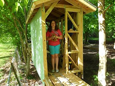
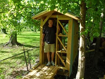
Both sides of the LT&P locomotive shed now have siding. The photos above were taken just before I added the last two pieces of T-111 to the east side. My daughter was helping as we painted, drilled and screwed the siding to the structure. The kids will be painting camouflage colors on the sides, although I started with a light green as you see in the photos.
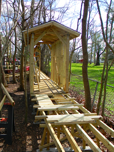
By mid May of 2012, I had almost reached the northernmost part of the railroad. In fact, after I took this photo I managed to install stringers all the way to the closest pier. The next pier will be a heavy duty one for a draw bridge needed to allow me and the horses to access the northern quarter of the property.
Summer 2012
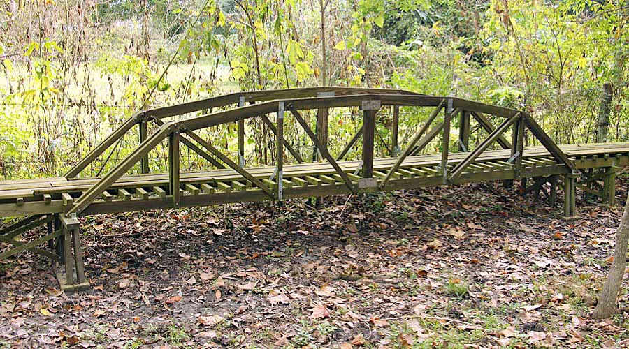
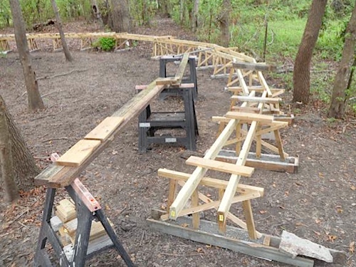
Here is the design and some photos of the first bridge on the northern loop built according to Lisa Eldredge's design. Lisa is an engineer with my company. I plan to call the bridge Eldredge Crossing! The 2x4 stringers were very bouncy after I had placed the ties, rails and deck boards. After I flipped the bridge over to add the trusses, that changed. I honestly cannot detect any deflection at all, even with a 200 pound locomotive, 80 pound caboose and my 125 pound son on the bridge.
I guess the bridge weighs around 200-250 pounds! I put hinges on it so I could fold it back out of the way. But after folding it back once and nearly having a disaster, I am re-thinking this. One benefit of the hinges is that they keep the end lined up very precisely with the trestle approaching the bridge. When my son and I ran the train over the joint, we could barely hear the click-clack of the joint. You may notice that the truss in the last photo is connected to the end of the 2x4 by only one bolt; it will get one more on each end. The other side already has two 1/4" bolts on each end.
Jul 2012
Jul 2012
Jul 2012
Sep 2012
Fall 2012
Sep 2012
Sep 2012
Sep 2012
Sep 2012
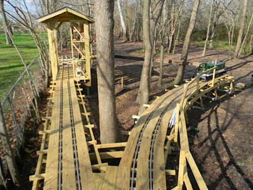
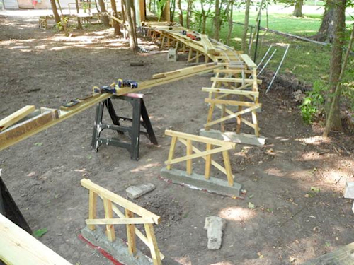
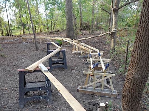
Below is the look of things on Friday, October 5. It's the first photo to show all the piers for the trestle in place, although I had not yet finished adding the stringers that hold the ties and rails. I put the rails in place so I could lay out the last couple of piers to follow the transition from the straight segment in the foreground to the radius for the loop about 20 feet away. Transitions help trains take curves more dependably.
A 12-foot draw bridge will soon span this gap (below, right). I need a drawbridge so I can access the northern parts of my property and to let our horses roam the whole yard. I installed the pier in the foreground January 2, 2012. Even though I used a level that is about 10 inches long, the height of the last pier was only off by about 1/8 inch! My son James and I went to Home Depot yesterday and got enough aluminum to build the truss for this bridge. God willing, we will be riding the entire railroad by October 14! I plan to hold a "Golden Spike" ceremony to complete the railroad. Actually, it would be a "Golden Screw" ceremony, since I use screws to hold the rails!
Oct 2012
Oct 2012
Spring 2017
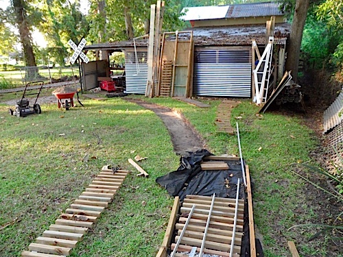
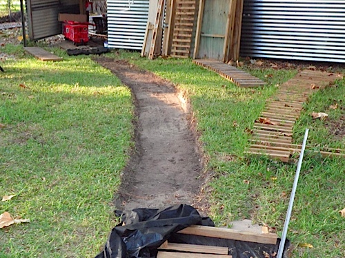
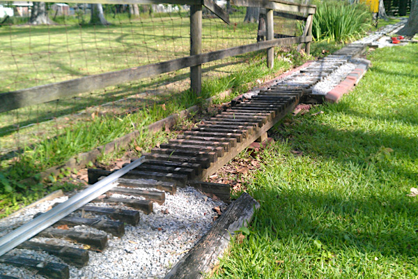
One of the oldest parts of the railroad was showing signs of its age. Of course, in south Louisiana moisture takes its toll. I had built two short bridges from 2x4s. This photo shows the old bridge on the south end right after I took most of the rails off. This bridge was in bad shape, with about two feet of one 2x4 completely rotten.
The biggest challenges turned out to be removing the ballast and fill in the 10-foot-long center section between the two short bridges, and moving the truss span that used to be in the horse yard to serve as the main span.
May 2017
The photo on the left, below,shows the stretch with the old bridges removed and about half of the center section dug out. If you look at the top right part of the photo, you can see one of the wheelbarrow loads of ballast. I took out three loads of ballast and two loads of sand - all had been put in a low spot in the yard when I first started building the railroad (hence the bridges on either end).
The photo on the right, below, gives you a close shot of the new abutment on the north end. I added abutments of poured concrete to avoid the problems of sinking and shifting concrete blocks that arose on the original construction. The old wood retaining walls also had issues with deterioration.
May 2017
May 2017
Once the center section of fill was gone, I poured two footings for the truss span. These footings hold the truss span and the two new approach spans. I put a small steel plate in the wet concrete to hold the new spans in place. This photo, below, shows the truss span on the gondola car after I carefully and painstakingly moved it from the horse yard. This bridge originally spanned part of the north loop, but it was too heavy to move as often as I wanted to operate or let the horses run.
May 2017
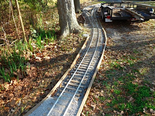
My daughter Price helped me move the truss from the gon to its final spot, photo 882. After the second short span went in, the new set up was nearly done in photo 884. I added deck boards to the new bridge to facilitate walking across, something that is almost as fun as riding. The approach spans are made with three 2x4s and ties made of engineered plastic wood - no more rotting here! It's all very solid and presentable. The truss span deserved to be a showpiece and its new location gives it that. I reused the original rails; I just bolted and screwed them back in, no fitting, cutting or drilling required. Now, and old, beat up part of the original construction looks new, more fun, and definitely more durable. Yes, I ran a train over it and was very pleased.
May 2017
May 2017
Fall 2017
Nov 2017
Nov 2017
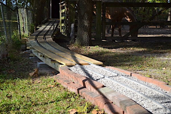
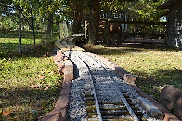
The revised grade on the LT&P is now complete: piers, rails and deck boards are all in place permanently. I tested the track with my NW-2 and it went up the hill much more smoothly than before. Of course, the test will be to pull a train of passengers. Another test will be to see how the steamer ascends the grade. It has only two powered axles (the NW-2 has four powered axles) and has historically been able to pull only the engineer and one person uphill, with difficulty.
Many of the ties in the ballasted stretch of track in the photos were the oldest on the railroad. I think they went in in 2009; originally, this stretch was very low and the ties stayed wet for long periods. The ones that were not already falling apart were quite soft and barely holding the screws. I replaced about 20 ties so far, using plastic balusters (made for deck construction).
In all, the new grade stretches for just over 60 feet, with a climb of 3%, if my calculations are right. This is one job I am glad is done!
Fall 2018
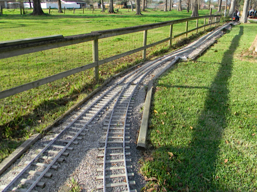
The LT&P has been working well with two trains running. The signal system guards the long stretch of single-track and looks great. However, when one engineer stops his or her train, it blocks the line. We had no place to pass, except the switching area on the north end of the railroad. An opportunity was presenting itself.
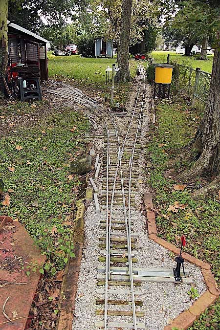
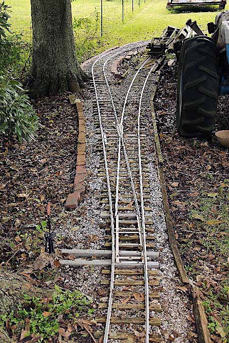
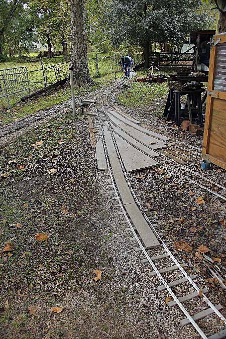
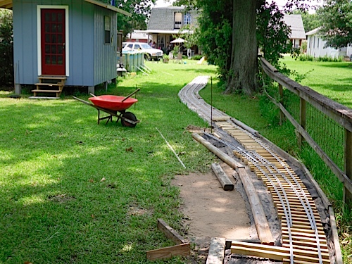
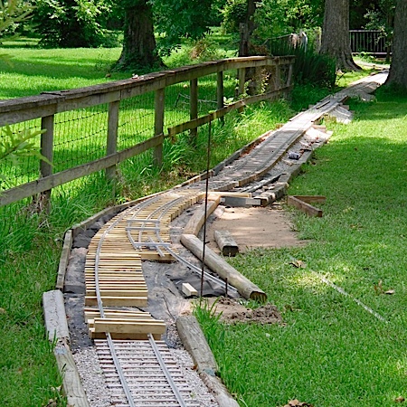
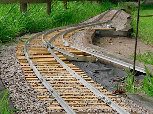
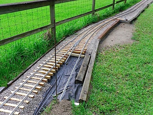
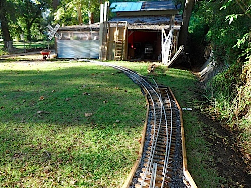
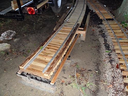
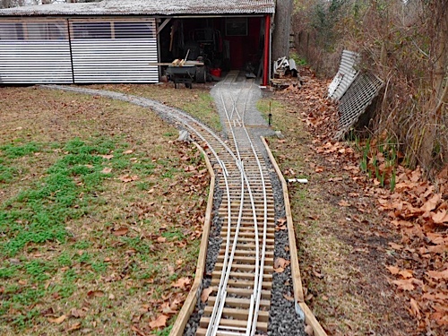
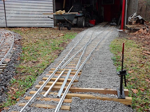
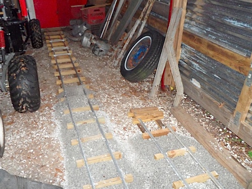
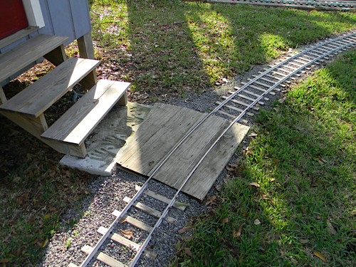
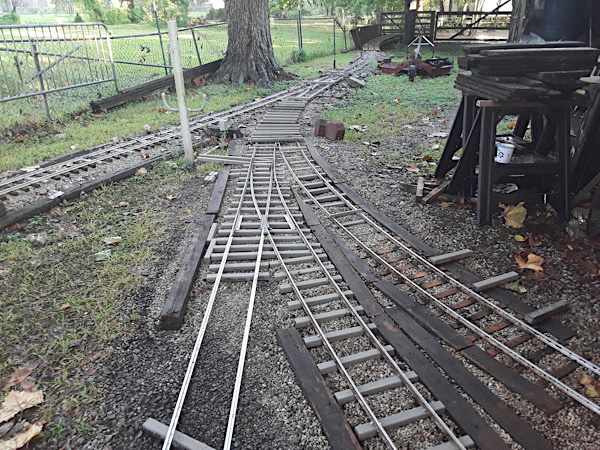
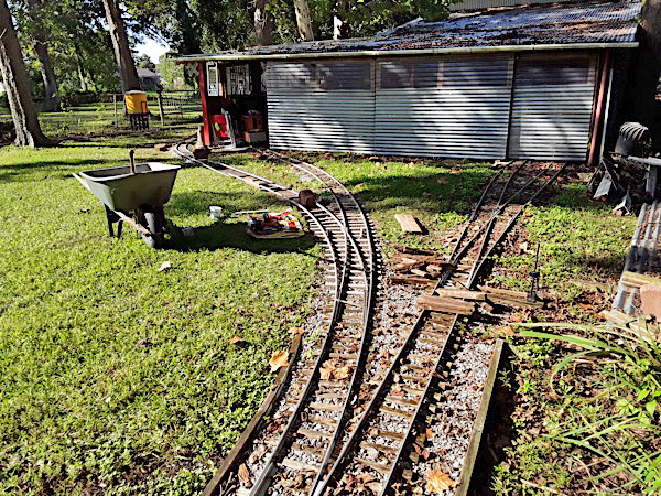
About three weeks ago, I started to install a passing siding by the barn, to allow engineers to park their trains, while leaving the line open for any other trains to continue running. The photo below shows the new switch at Hawkins Junction. When I removed the deck boards of the crossing, I discovered most of the original ties from 2010 were in bad shape, so I replaced them with new plastic ties (you can see I also laid out new ties for the next switch on the line). The next photo below shows the second new switch, near the storage tracks at right. The original line is the track that veers left and cuts under the corner of the barn. This switch and the new siding use all new plastic ties and I also replaced several rotten ties on the original track in this area.
Oct 2018
Oct 2018
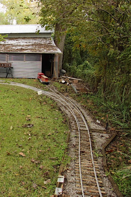
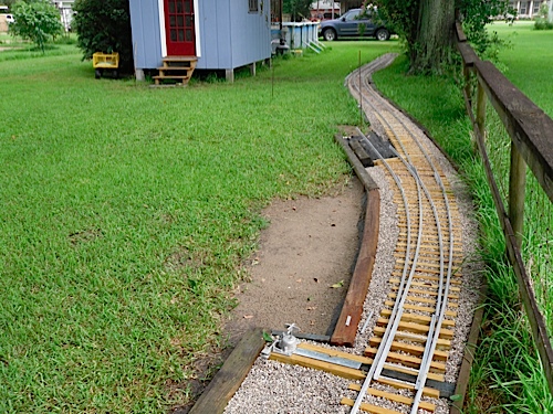
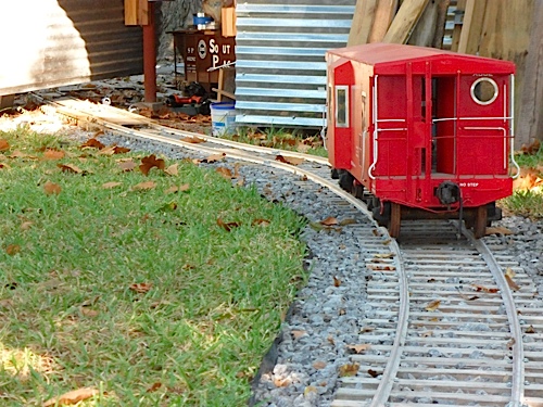
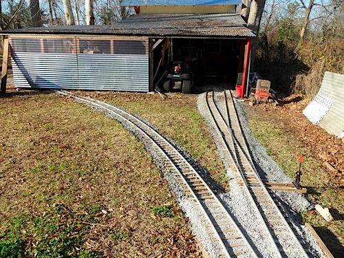
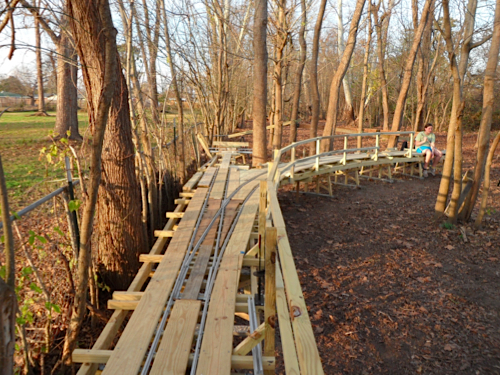
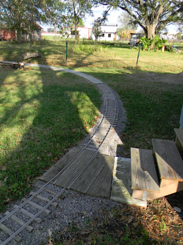
Finally, the photo below shows how the new track skirts the barn. I will be able to run a train without having to open up the barn doors. The new curves keep the LT&P minimum radius at 25 feet. The two siding tracks can each hold up to 30 feet of train.
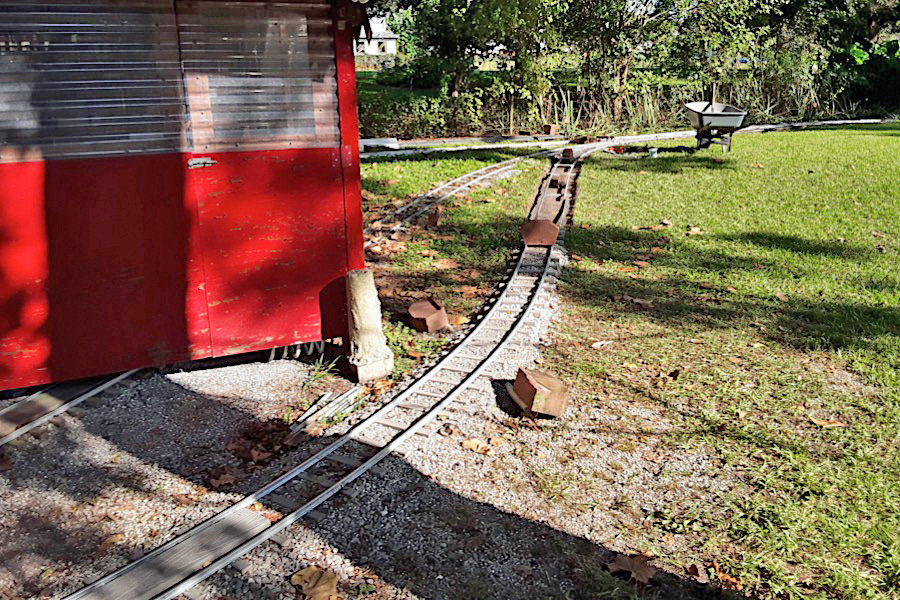
Oct 2018
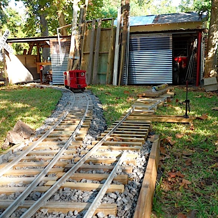
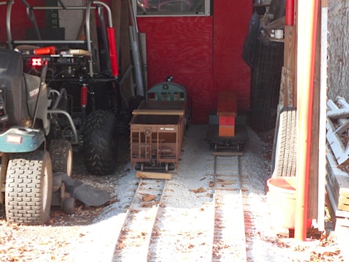
We ran trains Saturday and did some minor switching on the north loop. It added interest to drop off and pick up cars. The LT&P now has six cars that can be used for switching. This new siding on the south loop will ease congestion where we normally pick up and drop off passengers, and make it easier in the event we have more than two trains -- a dream that has yet to turn into reality -- but keep your fingers crossed that will change within a couple of months.
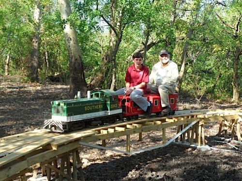
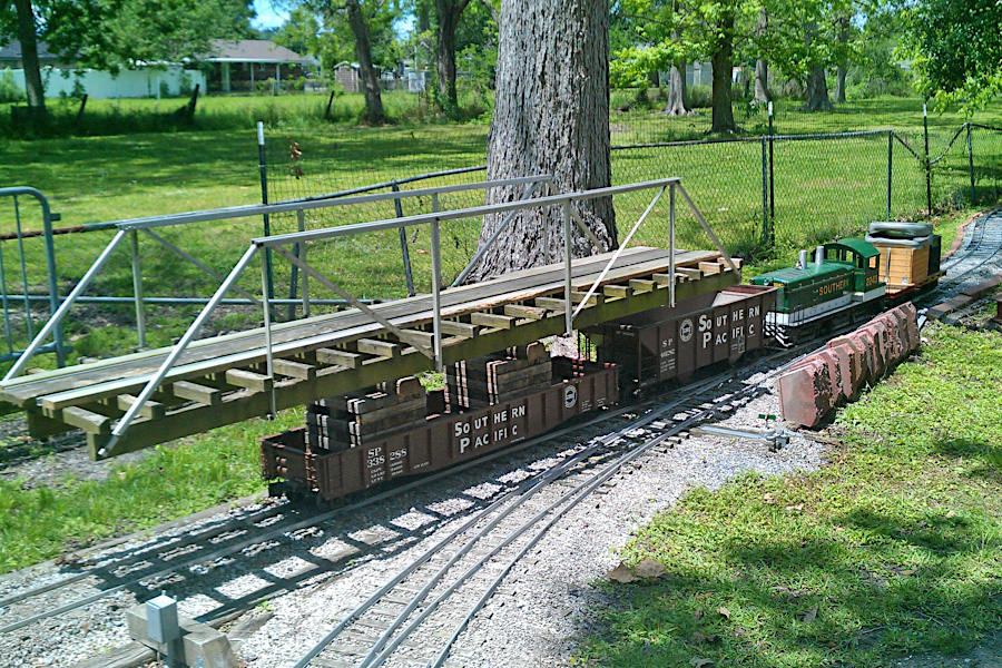
first run over the newly installed passing siding / Nov 2018 / RWH